
Dust compressing apparatus of vacuum cleaner

Inactive Publication Date: 2008-10-30
SAMSUNG GWANGJU ELECTRONICS CO LTD
View PDF16 Cites 61 Cited by
  • Summary
  • Abstract
  • Description
  • Claims
  • Application Information

AI Technical Summary

Benefits of technology

[0009]An aspect of the present disclosure is to address at least the above problems and / or disadvantages and to provide at least the advantages described below. Accordingly, an aspect of the present disclosure is to provide a dust compressing apparatus of a vacuum cleaner capable of automatically compressing dust or dirt collected in a dust separating unit and at the same time, easily dumping the dust or dirt collected in the dust separating unit.

Problems solved by technology

Thus, the conventional cyclone dust separating apparatus presents a problem that the dust or dirt is apt to scatter along with the whirling air and to flow backward into the cyclone again and as a result, a dust-separating efficiency is deteriorated.
In addition, since the dust or dirt is loosely accumulated in the dust bin, a time that the dust bin is filled with the dust or dirt is not only shortened, so that a user should frequently empty the dust or dirt from the dust bin, but also a problem may occur, in that when the dust bin is emptied, the dust or dirt loosely accumulated in the dust bin is scattered to contaminate the surroundings.
Thus, the above dust compressing apparatus is disadvantageous in that it is difficult to remove the dust or dirt compressed in the dust bin.
However, the dust compressing apparatus as described above is disadvantageous in that to compress the foreign substance in the dust collection container, the user should manually pull out the pressing member from the handle and then insert the pressing member by pushing it into the bar.

Method used


Image

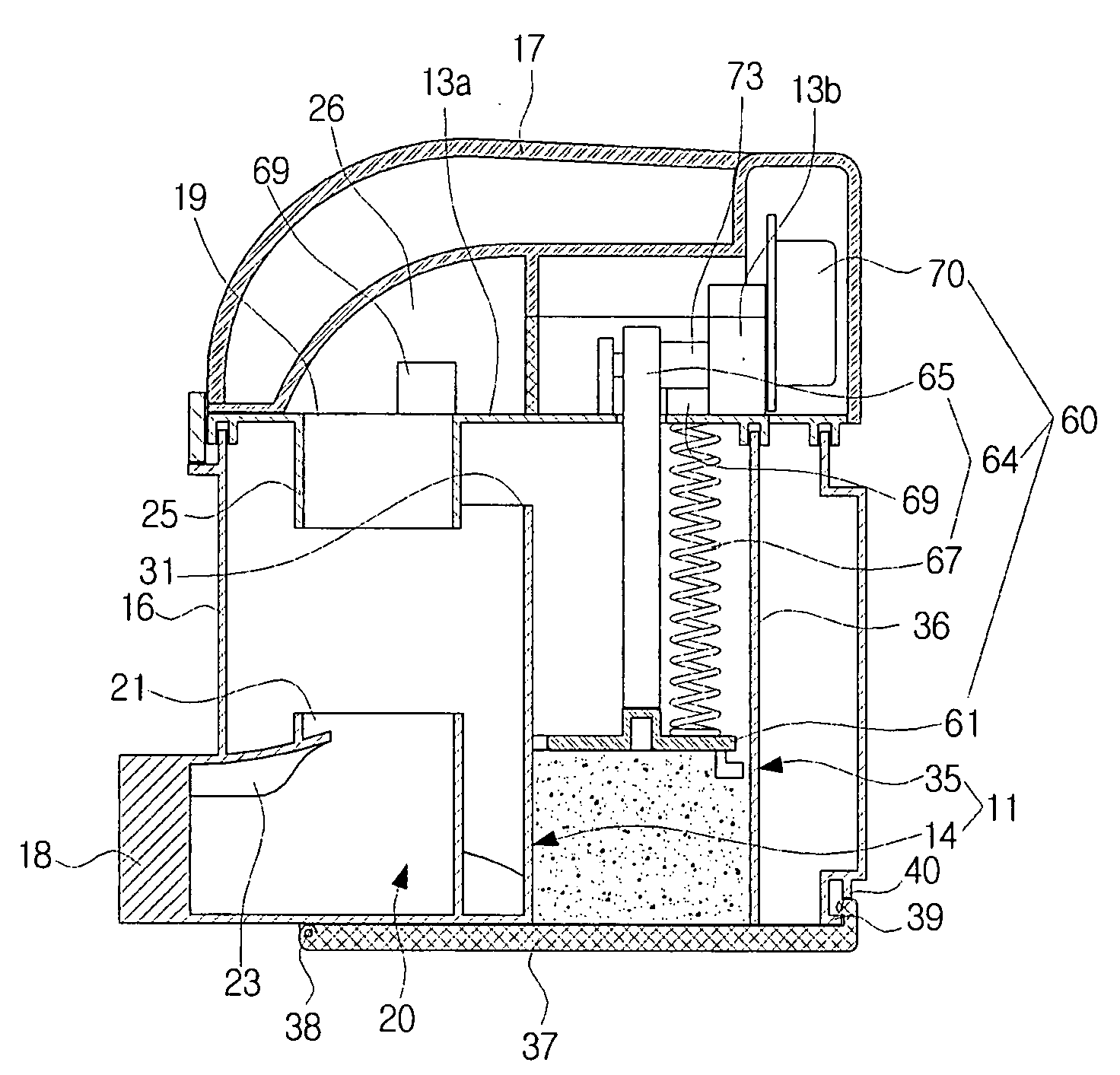
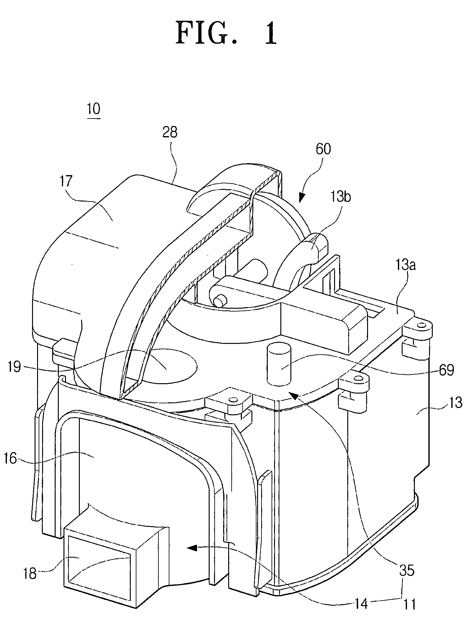
  • Dust compressing apparatus of vacuum cleaner
  • Dust compressing apparatus of vacuum cleaner
  • Dust compressing apparatus of vacuum cleaner

Examples


Embodiment Construction

[0023]Hereinafter, a dust compressing apparatus of a vacuum cleaner according to exemplary embodiments of the present disclosure will be described in detail with reference to the accompanying drawing figures.

[0024]FIGS. 1, 3A and 3B are a partially cut-away perspective view and cross-sectional views exemplifying a cyclone dust separating apparatus of a vacuum cleaner to which a dust compressing apparatus according to an exemplary embodiment of the present disclosure is applied.

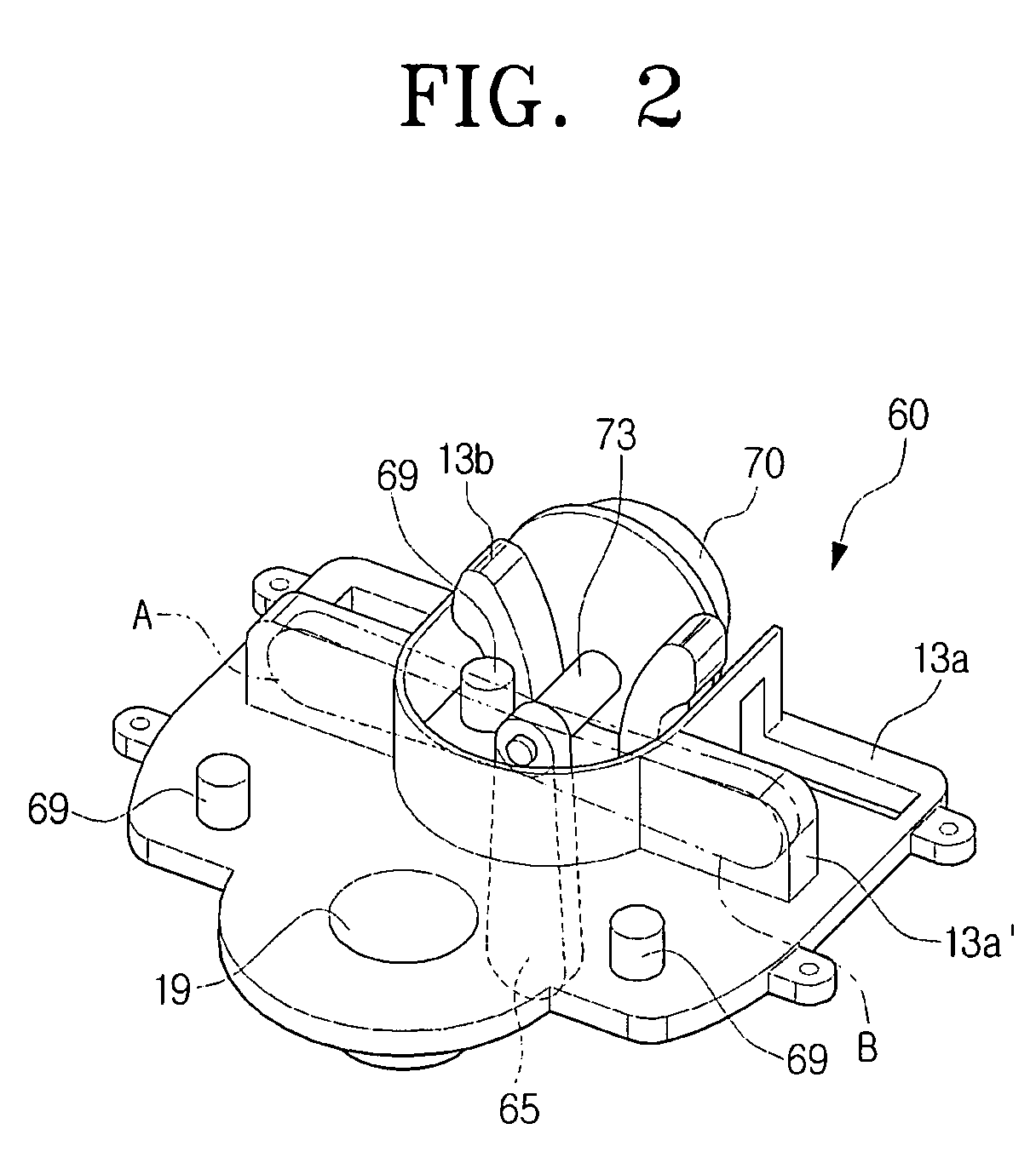
[0025]Referring to FIGS. 1, 3A and 3B, the cyclone dust separating apparatus 10 of the vacuum cleaner of the present disclosure includes a dust separating unit 11 to separate and collect dust or dirt from air by using a suction force of a suction motor (not illustrated) of the vacuum cleaner, and a dust compressing apparatus 60 according to the exemplary embodiment of the present disclosure to compress the dust or dirt collected in the dust separating unit 11.

[0026]The dust separating unit 11 is provided with ...


PUM

PropertyMeasurementUnit
Shapeaaaaaaaaaa

Abstract

A dust compressing apparatus of a vacuum cleaner capable of automatically compressing dust or dirt collected in a dust separating unit is disclosed. The dust compressing apparatus includes a compressing plate to compress dust or dirt collected in a dust separating unit, a moving unit disposed on one side of the dust separating unit located in an opposite direction to a direction where the compressing plate compresses the dust or dirt, to move the compressing plate to a compressing position of compressing the dust or dirt and a releasing position of moving away from the dust or dirt, and a driving motor to drive the moving unit thus to move the compressing plate to the compressing position.

Description

CROSS-REFERENCE TO RELATED APPLICATIONS[0001]This application claims the benefit under 35 U.S.C. § 119 of U.S. Provisional Patent Application No. 60 / 926,832, filed Apr. 30, 2007, in the United States Patent and Trademark Office, and Korean Patent Application No. 10-2007-0059494, filed on Jun. 18, 2007, in the Korean Intellectual Property Office, the entire contents of which are hereby incorporated by reference.BACKGROUND OF THE INVENTION[0002]1. Field of the Invention[0003]The present disclosure relates to a vacuum cleaner. More particularly, the present disclosure relates to a cyclone dust separating apparatus of a vacuum cleaner, which draws in external air and separates dust or dirt from the drawn-in air.[0004]2. Description of the Related Art[0005]In general, a cyclone dust separating apparatus provided in a vacuum cleaner is an apparatus, which whirls air laden with dirt or dust and separates the dirt or dust therefrom. Such a cyclone dust separating apparatus has been recently...

Claims


Application Information

Patent Timeline
IPC IPC(8): B01D46/42B01D45/12
CPCA47L9/108
Inventor OH, JANG-KEUNJUNG, IL-DUKIM, MIN-HA
Owner SAMSUNG GWANGJU ELECTRONICS CO LTD
Learn More