Rotary Engine

Inactive Publication Date: 2008-10-30
MAENG HYUK JAE
View PDF26 Cites 2 Cited by
  • Summary
  • Abstract
  • Description
  • Claims
  • Application Information

AI Technical Summary

Benefits of technology

[0017]In a rotary engine of the present invention, complete combustion of fuel is realized, and explosive combustion power is transmitted to an output shaft without power loss, thus maximizing the efficiency of the engine. As well, the rotary engine of the

Problems solved by technology

Conventional reciprocating piston engines, in which compression, combustion and expansion strokes are conducted in a single cylinder, are disadvantageous in that excessive kinetic energy loss is incurred by reciprocating motion of the piston, high-speed rotation is difficult, and output power is low compared to the size of the engine.
However, the gas turbine engine has a structure in which out

Method used


Image

  • Rotary Engine
  • Rotary Engine
  • Rotary Engine

Examples


Embodiment Construction

[0031]Hereinafter, a rotary engine according to a preferred embodiment of the present invention will be described in detail with reference to the attached drawings.

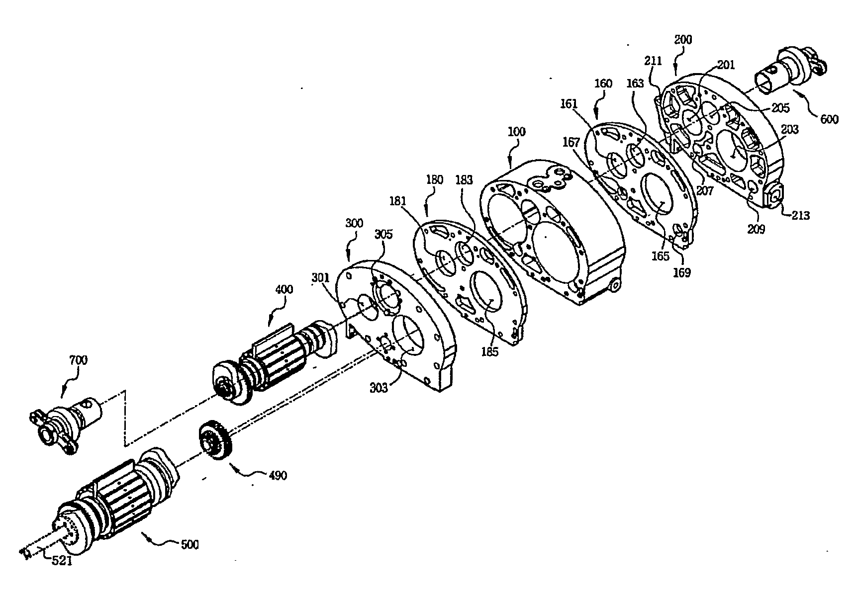
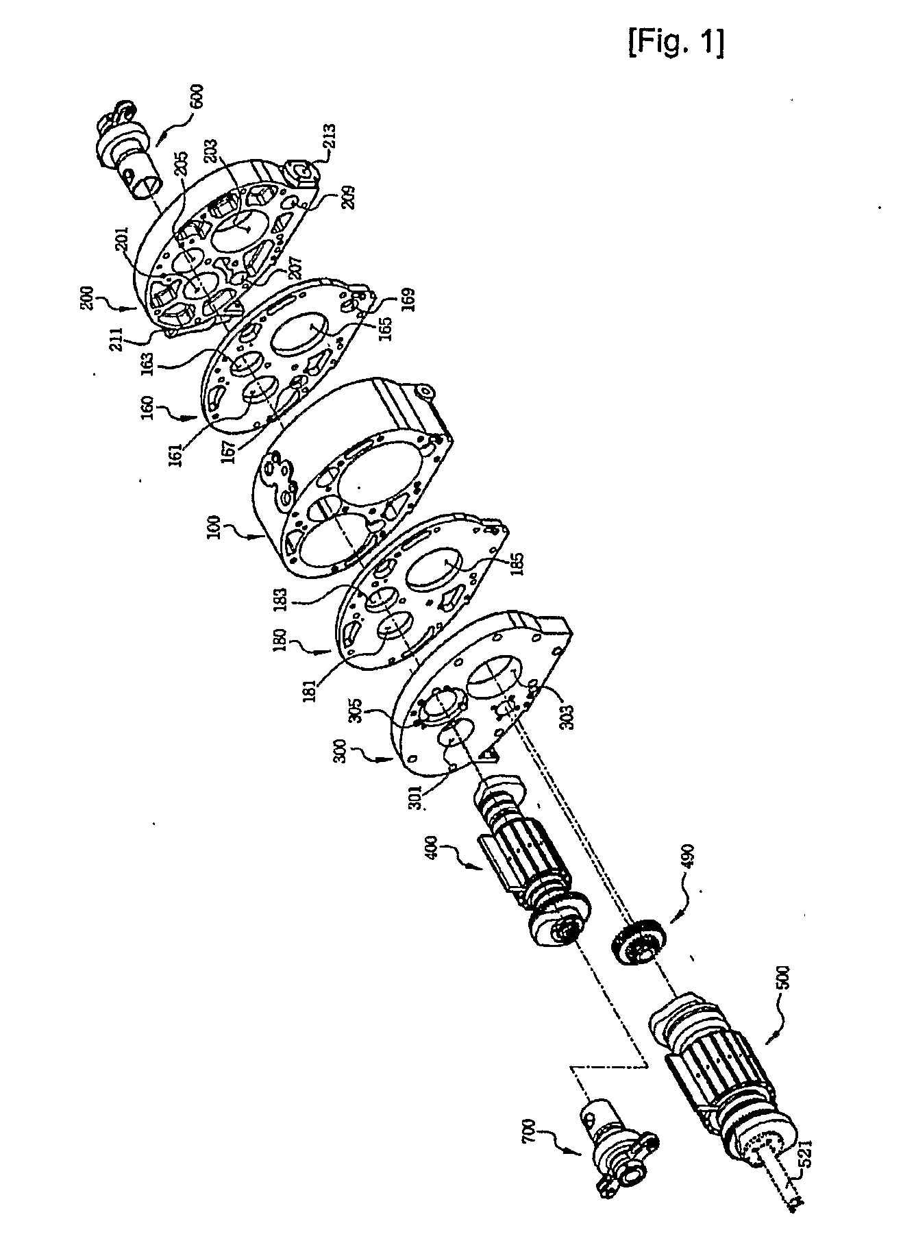
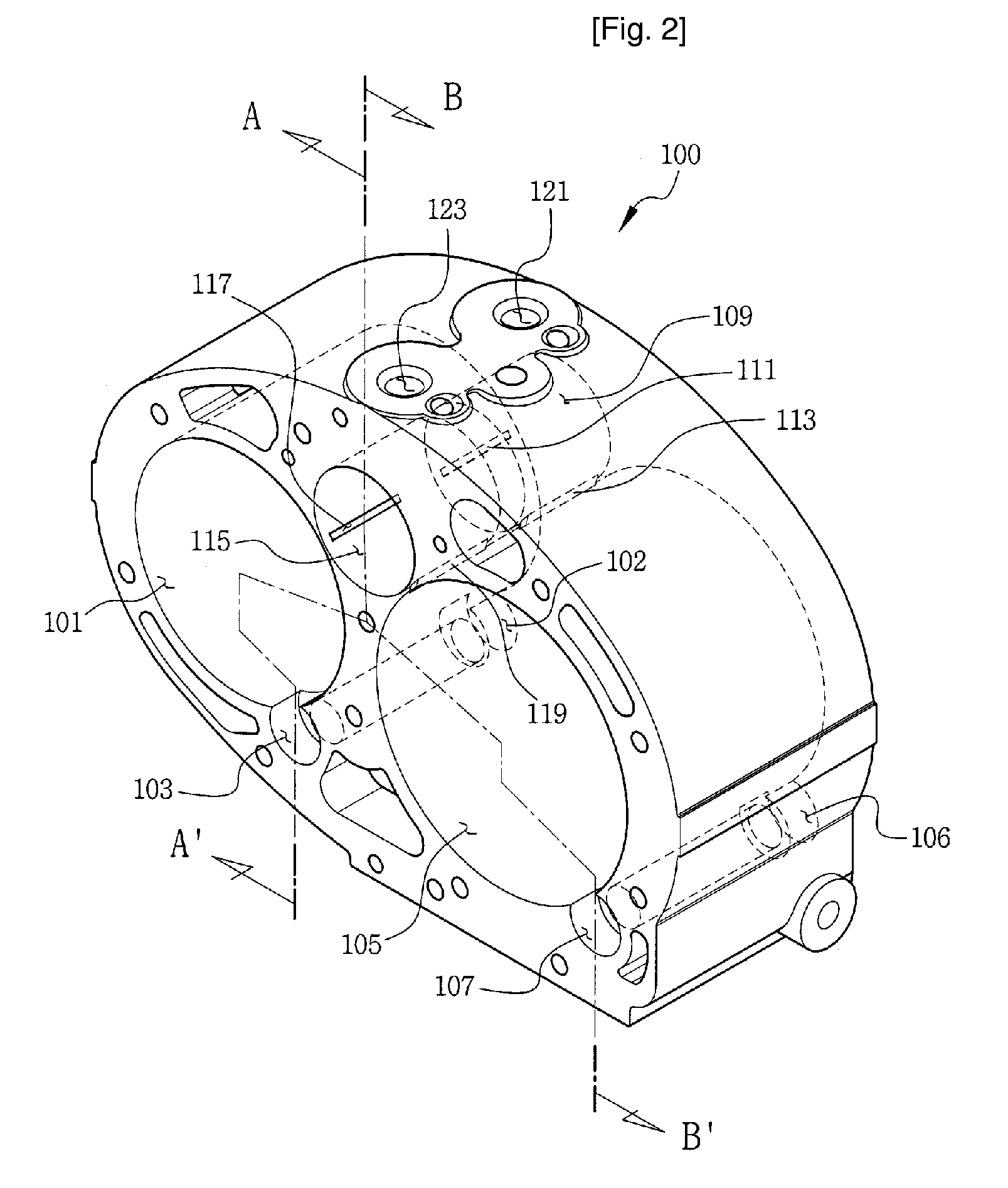
[0032]FIG. 1 is an exploded perspective view of a rotary engine, according to an embodiment of the present invention. FIG. 2 is a perspective view of an engine body 100 of the rotary engine. FIG. 3 is a sectional view taken along the line A-A′ of FIG. 2. FIG. 4 is a sectional view taken along the line B-B′ of FIG. 2. FIG. 5 is a perspective view showing a compression rotor 400 of the rotary engine. FIG. 6 is a perspective view showing an output rotor 500 of the rotary engine. FIG. 7 is a perspective view showing a valve 600 of the rotary engine. FIG. 8 is a front view showing the valve 600 of the rotary engine. FIG. 9 is a partially broken perspective view showing a valve body 601 of the valve 600. FIG. 10 is an assembled perspective view showing a main shaft (power transmission shaft) side of the rotary engine. FIG. 11 i...


PUM


Abstract

A rotary engine is disclosed. The rotary engine of the present invention includes an engine body (100), which has therein a compression chamber (101), an output chamber (105) and a combustion chamber (109, 115), which is formed between the compression chamber and the output chamber. The rotary engine further includes a compression rotor (400) which is eccentrically provided in the compression chamber, an ignition device (125, 126) which is provided in the combustion chamber of the engine body, and an output rotor (500), which is eccentrically provided in the output chamber. The rotary engine further includes valves (600) which are provided in the respective bores of the combustion chamber, a synchronizing means for rotating the compression rotor in conjunction with rotation of the output rotor, and an axial sealing means for sealing the compression chamber, the combustion chamber and the output chamber.

Description

TECHNICAL FIELD[0001]The present invention relates, in general, to rotary engines and, more particularly, to a rotary engine which prevents the loss of kinetic energy occurring in engines using reciprocating pistons or propellers, thus maximizing the thermal efficiency of the engine.BACKGROUND ART[0002]Conventional reciprocating piston engines, in which compression, combustion and expansion strokes are conducted in a single cylinder, are disadvantageous in that excessive kinetic energy loss is incurred by reciprocating motion of the piston, high-speed rotation is difficult, and output power is low compared to the size of the engine. Gas turbine engines and wankel engines, which are kinds of rotary engines, are representative examples of engines which were developed to overcome the disadvantages of the reciprocating piston engines. Typically, the conventional gas turbine engines consist of three parts: a compressor, a combustion chamber, and a turbine, and have a structure in which, ...

Claims


Application Information

Patent Timeline
IPC IPC(8): F02B53/00
CPCF01C1/3442F01C11/004F01C19/02F01C21/18F01L1/026F01L1/08F01L7/021F02B53/06Y02T10/17Y02T10/12A61L2/18A61L2/22A61L2202/15A61L2202/26B05B1/005B05B13/0278B05B13/04B08B5/02
Inventor MAENG, HYUK-JAE
Owner MAENG HYUK JAE
Why Eureka
Try Eureka