Multiple path variable speed constant frequency device having automatic power path selection capability

a variable speed constant frequency, multi-path technology, applied in the direction of electric generator control, dynamo-electric converter control, instruments, etc., can solve the problems of negligible power loss and inability to generate power at the required frequency, so as to maximize the efficiency of the engine generator, enhance fuel economy, and save fuel

Inactive Publication Date: 2005-01-18
PILLER USA INC
View PDF31 Cites 77 Cited by
  • Summary
  • Abstract
  • Description
  • Claims
  • Application Information

AI Technical Summary

Benefits of technology

These and other objects of the present invention are accomplished in accordance with the principles of the invention by providing a multi-path VSCF device that maximizes the efficiency of an engine generator based on the load, engine, or other desired operating characteristics. The multi-path VSCF device enables the engine generator to operate at different speeds, depending on the load. Because loads typically cycle between high and low demand, the engine generator does not have to operate at the same speed to generate power required for the load. The VSCF device enables the engine generator to slow down during low-loads, thereby conserving fuel. Thus, the present invention enhances fuel economy and reduces noise and air pollution.

Problems solved by technology

Moreover, power loss is negligible when power is delivered to the load through the standard line path because there is no loss attributable to the converter pair.
When the engine slows down, however, it may not be able to generate power at the required frequency.

Method used


Image

  • Multiple path variable speed constant frequency device having automatic power path selection capability
  • Multiple path variable speed constant frequency device having automatic power path selection capability
  • Multiple path variable speed constant frequency device having automatic power path selection capability

Examples


Embodiment Construction

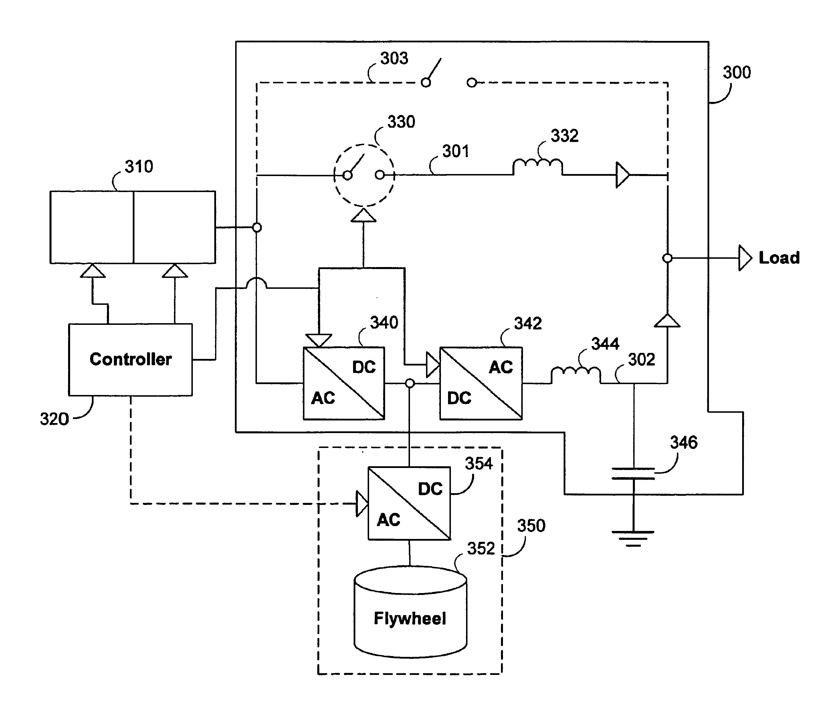
FIG. 3 illustrates a multi-path variable speed constant frequency (“VSCF”) device 300 which is in accordance with the principles of the present invention. FIG. 3 shows engine generator 310 connected to VSCF device 300 so that generated power can be provided to the load via line inductor path 301 and VSCF path 302. If desired, optional bypass path 303 may provide yet another path for delivering power to the load. Persons skilled in the art will appreciate that other specialized circuit paths may also be used, in which case they would be connected in parallel between the engine generator and the load, without departing from the spirit of the present invention.

Engine generator 310 is well known in the art. A typical engine generator 310 includes an engine (e.g., diesel or natural gas engine) and a generator. The engine operates as a prime mover that rotates, for example, a shaft coupled to the generator. As the shaft rotates, electrical power is generated and provided to the load.

In ge...


PUM


Abstract

The present invention relates to variable speed constant frequency (VSCF) devices and methods for maximizing engine generator efficiency. In one embodiment, a VSCF device may include at least two paths for conducting power to the load. One path, a line inductor path, may advantageously incur minimal power loss when the engine generator is supplying rated power to a load. A second path, a VSCF path, may be used to ensure that the frequency of the power is maintained at a substantially constant frequency under various load conditions. Another embodiment of the invention describes a process for determining optimal engine generator speed for a particular load. Because engine speed can be varied using any VSCF device, this process determines a speed that minimizes fuel consumption, emissions, and noise pollution for a given load.

Description

BACKGROUND OF THE INVENTIONThe present invention relates to variable speed constant frequency devices and methods for maximizing engine generator efficiency. In particular, the present invention relates to maximizing the efficiency of an engine generator using a multi-path variable speed constant frequency device.Engine generators are typically used to provide power independent of that provided by a public utility. Engine generators may be used, for example, as primary power generators that provide a reliable source of power for industrial, commercial, and residential applications. For example, an industrial application such as a high value manufacturing process may require a reliable source of electricity to ensure that product development (e.g., semi-conductor fabrication) is not damaged by power fluctuations or power loss (e.g., caused by transmission line malfunction). A mining operation that is too remote to access a utility power grid may require an engine generator to provide...

Claims


Application Information

Patent Timeline
Patent Type & Authority Patents(United States)
IPC IPC(8): H02J7/14H02P9/48H02P9/00H02P9/04
CPCH02J7/1446H02J7/1492H02P9/48H02P9/04Y02T10/92
Inventor PINKERTON, III, JOSEPH F.BADGER, DAVID A.
Owner PILLER USA INC
Why Eureka
Try Eureka