Electric field generating apparatus for combustion chamber

a technology of electric field and combustion chamber, which is applied in the direction of mechanical equipment, combustion air/fuel air treatment, machines/engines, etc., can solve the problems of limiting the increase of fuel consumption rate, unable to achieve performance, and regulated combustion timing of gasoline engines in a very limited range, so as to improve combustion efficiency, prolong combustion time, and accelerate flame propagation speed

Active Publication Date: 2013-06-13
HYUNDAI MOTOR CO LTD +1
View PDF6 Cites 2 Cited by
  • Summary
  • Abstract
  • Description
  • Claims
  • Application Information

AI Technical Summary

Benefits of technology

[0038]According to the exemplary embodiments of the present invention, an electric field generating apparatus for a combustion chamber enhances combustion efficiency with a flame propagation speed delayed or promoted due to an influence of electric fields applied when flames are formed within the combustion chamber, thereby significantly increasing engine output and efficiency as compared to the same condition and lowering a fuel consumption rate, and maximizing an overall engine efficiency as well.
[0039]Further, the present invention delays a flame propagation speed in a region where combustion efficiency is increased in case of a low flame propagation speed within the combustion chamber and promotes a flame propagation speed in a region where combustion efficiency is increased in case of a high flame propagation speed, thereby maximizing engine efficiency as compared to the same condition due to maximization of combustion efficiency of an entire region.

Problems solved by technology

Due to such a contradictory operation, an ignition timing of a gasoline engine is regulated in a very limited range.
However, if the reverse effect due to a delay of an ignition timing is solved by increasing an amount of fuel with respect to an air / fuel ratio, there occurs a limit where a fuel consumption rate increases due to the increased amount of fuel.
However, the above-mentioned methods of enhancing combustion efficiency have limits respectively and thus cannot reach a performance to be achieved.
As an example, the spark plug has a limit where a method of utilizing a local ionizing effect through change in shape, adjustment of a gap, and regulation of applied voltage and current achieves the effect only in a local region, and a lean-burn engine is disadvantageous in aspects of cost and management since it requires an additional substance in addition to a gasoline fuel.
In particular, although the patent document uses electric fields, as the electric fields are used to reduce the sizes of fuel particles, there is a basic limit where a fuel efficiency enhancing effect through an interaction between electric fields and combustion flames within a combustion chamber cannot be accomplished at all.

Method used


Image

  • Electric field generating apparatus for combustion chamber
  • Electric field generating apparatus for combustion chamber
  • Electric field generating apparatus for combustion chamber

Examples


Embodiment Construction

[0048]Reference will now be made in detail to various embodiments of the present invention(s), examples of which are illustrated in the accompanying drawings and described below. While the invention(s) will be described in conjunction with exemplary embodiments, it will be understood that present description is not intended to limit the invention(s) to those exemplary embodiments. On the contrary, the invention(s) is / are intended to cover not only the exemplary embodiments, but also various alternatives, modifications, equivalents and other embodiments, which may be included within the spirit and scope of the invention as defined by the appended claims.

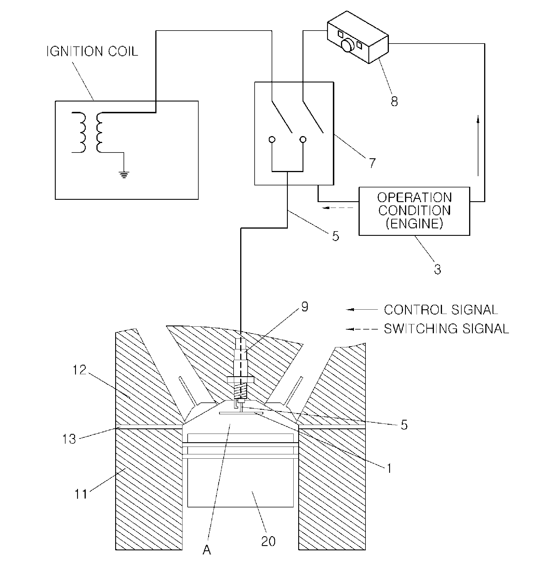
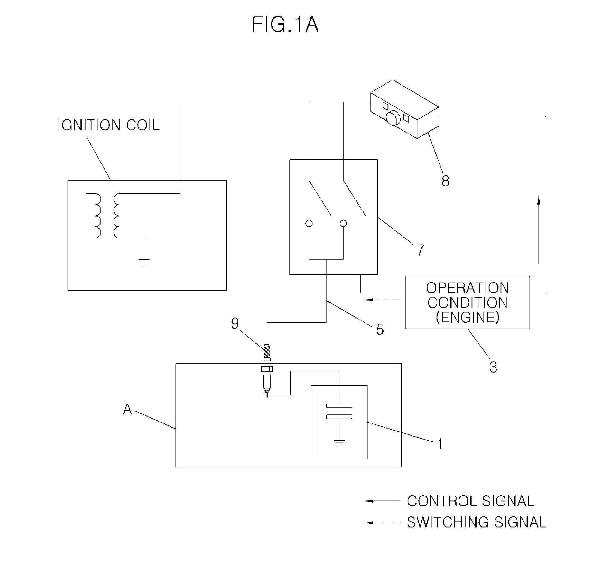
[0049]Referring to FIG. 1A, an electric field generating apparatus for a combustion chamber includes an electric field generator 1 made of a conductive material to which a high voltage is applied to create electric fields within a space of a combustion chamber A, a lead-in wire 5 applied as a conductor to flow a high voltage to electr...


PUM


Abstract

An electric field generating apparatus for a combustion chamber, may include an electric field generator located within a space of the combustion chamber where combustion flames may be produced to create electric fields within the space of the combustion chamber through an applied predetermined voltage, a lead-in wire connected to the electric field generator to flow the predetermined voltage to the electric field generator, and a high voltage providing unit connected to the lead-in wire for selectively applying the predetermined voltage to the lead-in wire in accordance with an output signal of a controller generated depending on an operation condition of an engine.

Description

CROSS-REFERENCE TO RELATED APPLICATIONS[0001]The present application claims priority to Korean Patent Application Number 10-2011-0131752 filed Dec. 9, 2011, the entire contents of which application is incorporated herein for all purposes by this reference.BACKGROUND OF THE INVENTION[0002]1. Field of the Invention[0003]The present invention relates to a combustion chamber for an internal combustion engine, and more particularly, to an electric field generating apparatus for a combustion chamber which controls flame propagation speed with electric fields applied into the combustion chamber, thereby increasing engine output and maximizing combustion efficiency.[0004]2. Description of Related Art[0005]In general, since a fuel and air mixed at a specific ratio are introduced into a space of a combustion chamber to be compressed and are ignited by an ignition plug to be burned in a gasoline engine, flames cannot but propagate after ignition of a spark plug during an explosion stroke.[0006...

Claims


Application Information

Patent Timeline
Patent Type & Authority Applications(United States)
IPC IPC(8): F02P15/00
CPCF02P15/00F02P9/002F02B51/04F02M27/04F02P9/007F02P23/045
Inventor KIM, HONGBINKAUH, SANG KENCHOI, YOUN-SOKSHON, KYOUNG-MIN
Owner HYUNDAI MOTOR CO LTD
Why Eureka
Try Eureka