Linear Motor

a technology of linear motors and motors, applied in the direction of motor/generator/converter stoppers, dynamo-electric converter control, instruments, etc., can solve the problems of speed ripple reduction and reliability degradation of transfer apparatuses, and achieve the effect of enhancing motor thrust and effective

Inactive Publication Date: 2008-10-30
WAKO GIKEN
View PDF11 Cites 18 Cited by
  • Summary
  • Abstract
  • Description
  • Claims
  • Application Information

AI Technical Summary

Benefits of technology

[0011]It is an object of the present invention to provide a linear motor adaptive to various use environments, in which the effective magnetic flux density interlinking with the armature coil is increased, thereby enhancing the motor thrust.

Problems solved by technology

However, the control of interval K of the magnets can reduce the speed ripple, but is not proposed for increasing the thrust.
Consequently, the transfer apparatus will be degraded in reliability.

Method used


Image

  • Linear Motor
  • Linear Motor
  • Linear Motor

Examples


first embodiment

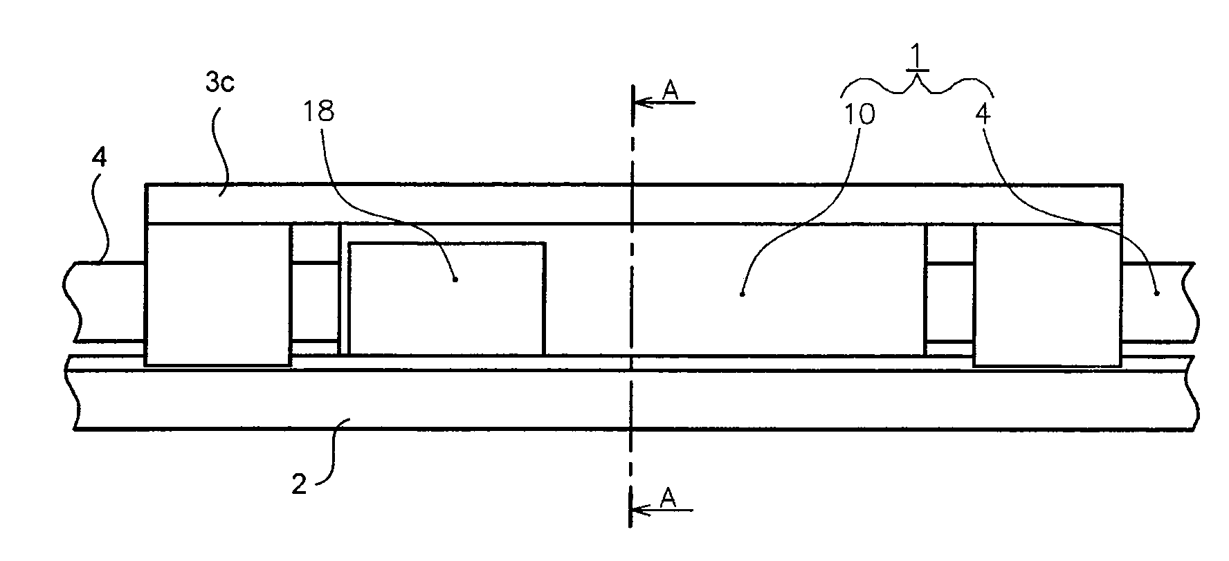
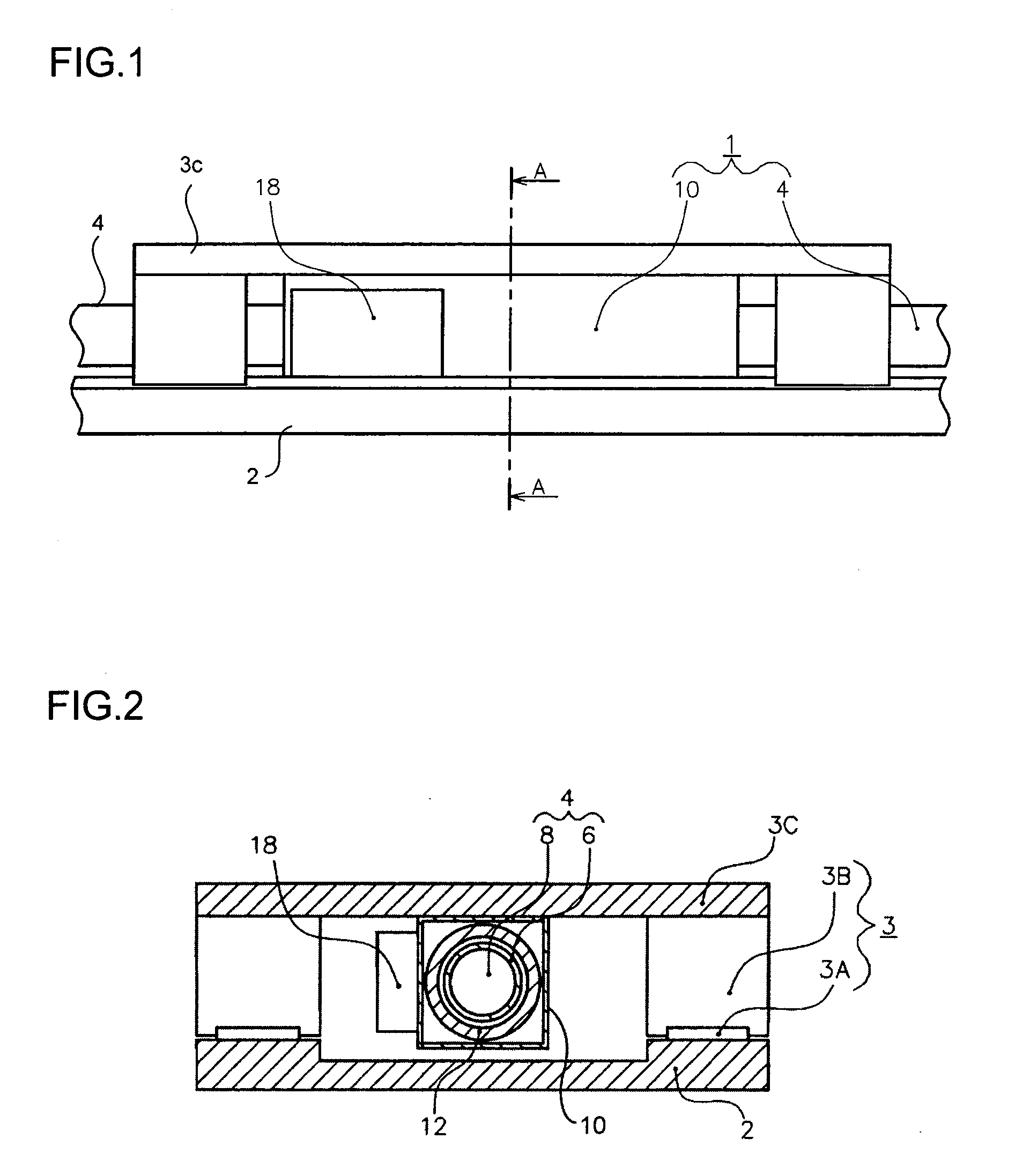
[0043]FIG. 1 is a front view outlining the configuration of a linear motor 1 according to a first embodiment of this invention, which employs a magnetic linear encoder. FIG. 2 is a sectional view taken along line A-A shown in FIG. 1.

[0044]As shown in FIGS. 1 and 2, the linear motor 1 comprises a base unit 2 and a linear guide 3. The linear guide 3 is designed to define a straight line in which the linear motor 1 can move. The guide 3 is composed of a guide rail 3A and a slider 3B. The guide rail 3A is secured to the base unit 2. The slider 3B can slide on the guide rail 3A. On the upper surface of the slider 3B, a table 3C is mounted to hold a machine or an apparatus that uses the linear motor 1.

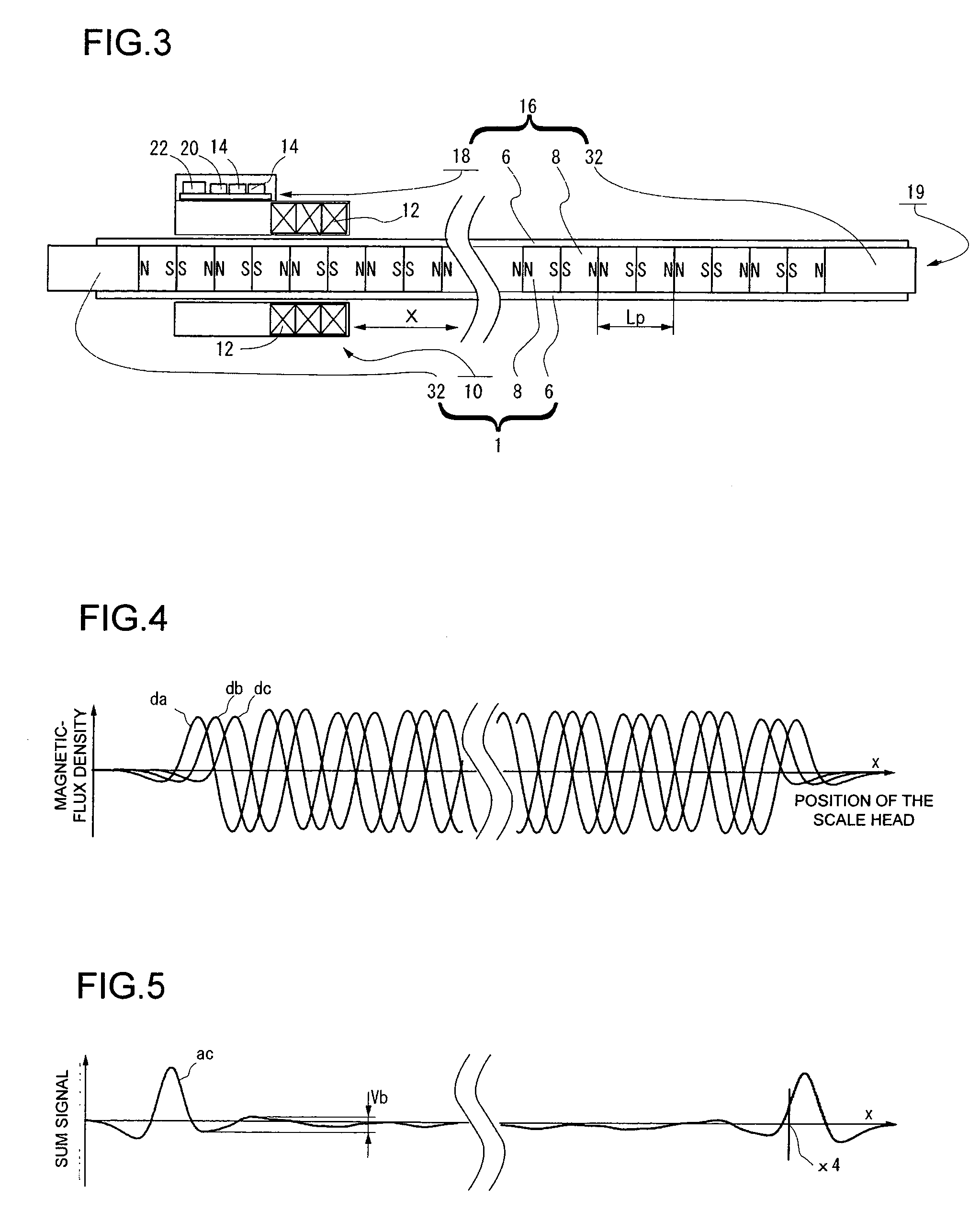
[0045]A field yoke 4 is arranged on the base unit 2. The field yoke 4 constitutes the stator (fixed unit) of the linear motor 1. The yoke 4 is configured to generate a magnetic field. The yoke 4 is composed of a hollow cylindrical member (sleeve) 6 and a row of permanent magnets 8 shaped lik...

second embodiment

[0079]A second embodiment of the present invention will be described. FIG. 15 depicts a linear motor 1a according to the second embodiment. The linear motor 1a differs in configuration from the linear motor 1 according to the first embodiment, in the following respects.

[0080]In the second embodiment, the permanent magnets are so arranged that each may have either pole contacting the same pole of either adjacent permanent magnet (the N poles of any two adjacent magnets abut therefore on each other, and so do the S poles thereof), thereby improving the arrangement and assembling of the permanent magnets and making the effective magnetic flux that extends across the armature coil more intensive than in the linear motor 1 according to the first embodiment. The linear motor according to the second embodiment therefore has an improved thrust.

[0081]Generally, the permanent magnets 8 incorporated in a linear motor can generate a very intense magnetic field if they are rare-earth magnets mad...


PUM


Abstract

A position-data converter and a motor-drive control device are connected. The position-data converter receives two-phase, sine-wave analog signals da and db from two first magnetic detectors, respectively, and converts these signals da and db to position data. On receiving a positioning instruction, the motor-drive control device calculates the value of current, from the current position signal generated by the position-data converter. The permanent magnets incorporated in a linear motor are used as components of a linear scale, as well.

Description

CROSS-REFERENCE TO RELATED APPLICATIONS[0001]This application is based upon and claims the benefit of priority from the prior Japan Patent Applications No. 2007-121942 filed on Apr. 5, 2007 No. 2007-131033 filed on Apr. 17, 2007 and No. 2008-061140 filed on Mar. 11, 2008, the entire contents of which are incorporated herein by reference.BACKGROUND OF THE INVENTION[0002]1. Field of the Invention[0003]The present invention relates to a linear motor, and more particularly to an improved linear motor that undergoes straight-line translation motion and is therefore useful as high-speed repeated positioning means.[0004]2. Description of the Related Art[0005]In the field of transfer apparatuses, linear motors have hitherto been used as drive sources in constant-speed positioning or high-speed positioning. Any linear motor comprises a stator and a movable member. The stator is composed of a hollow cylindrical member and a plurality of magnets arranged in row in the hollow cylindrical member...

Claims


Application Information

Patent Timeline
Patent Type & Authority Applications(United States)
IPC IPC(8): H02K41/02
CPCH02K29/08H02K41/03
Inventor SASAKI, TOSHIHIKOWATANABE, KAZUOISHIKAWA, KATSUMI
Owner WAKO GIKEN
Why Eureka
Try Eureka