
Method and algorithm for detecting movement of an object

a technology of object movement and method, applied in the field of method and algorithm for detecting movement of objects, can solve the problems of affecting the user's periodic affecting the user's typing experience, and requiring a rolling surface, so as to achieve the effect of preventing the user from periodically typing on the computer, disrupting and/or otherwise preventing the user from typing

Inactive Publication Date: 2008-10-30
SONY ERICSSON MOBILE COMM AB
View PDF8 Cites 90 Cited by
  • Summary
  • Abstract
  • Description
  • Claims
  • Application Information

AI Technical Summary

Benefits of technology

[0007]In view of the aforementioned shortcomings associated with user input devices, there is a need in the art for a contact-less user interface and an associated algorithm in electronic equipment that is capable of detecting and/or sensing user move

Problems solved by technology

The growing popularity of laptop or notebook computers has created a significant problem for mouse type technologies that require a rolling surface.
Adding to the problem is that a mouse usually needs to be moved over long distances for reasonable resolution.
Finally, a mouse requires the user to lift a hand from the keyboard to make the cursor movement, thereby disrupting and / or otherwise preventing a user from periodically typing on the computer.
A track ball is generally large in size and does not fit well in a volume-sensitive application such as a laptop computers or other small and / or portable electronic equipment.
There are drawbacks associated with user interfaces that require physical contact.
Such drawbacks include, densely populated user interfaces, difficult manipulation of the user interface due to physical size limitation of electronic equipment, difficult for users to view and / or otherwise manipulate densely populated user interfaces, etc.

Method used


Image

  • Method and algorithm for detecting movement of an object
  • Method and algorithm for detecting movement of an object
  • Method and algorithm for detecting movement of an object

Examples


Embodiment Construction

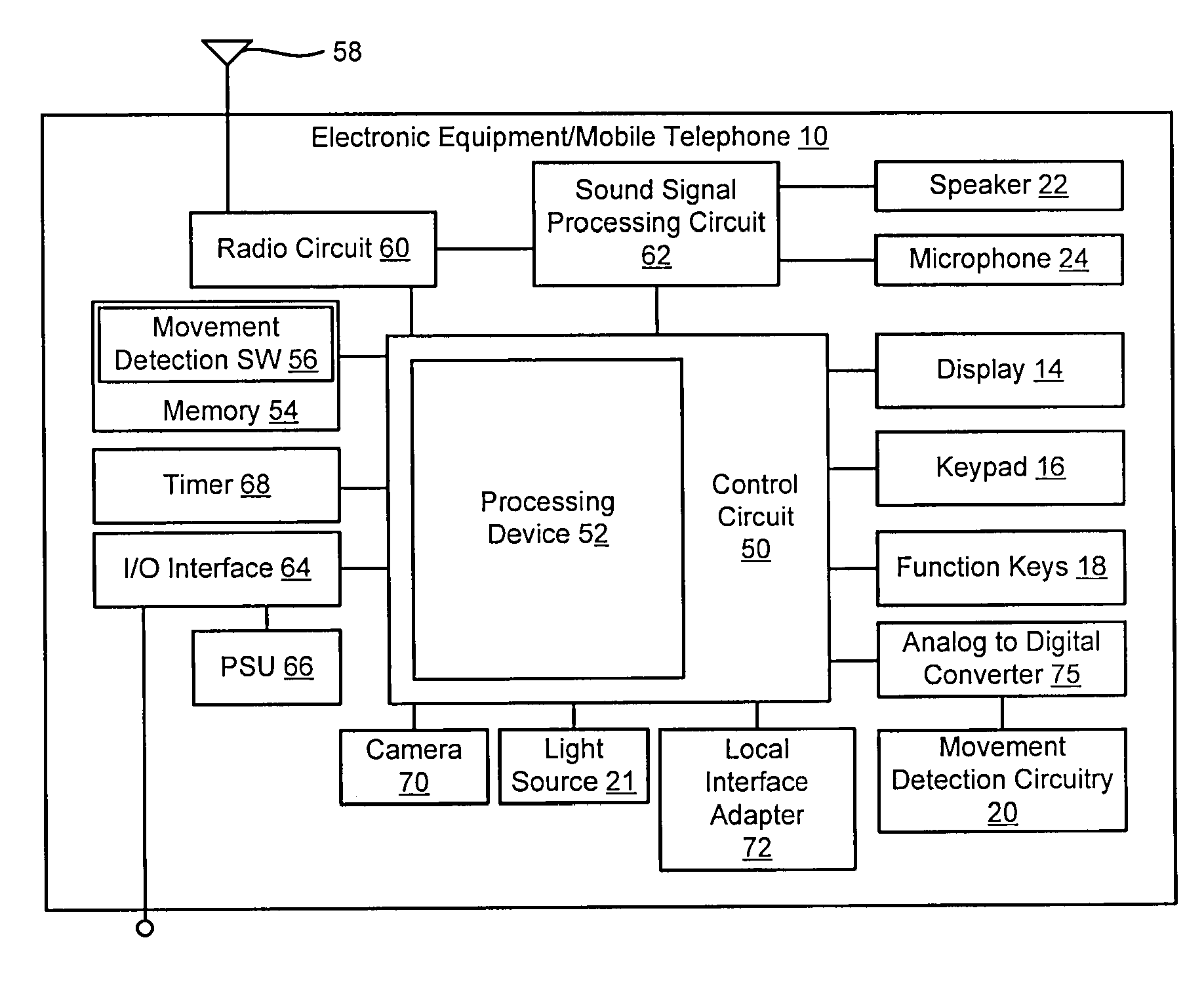
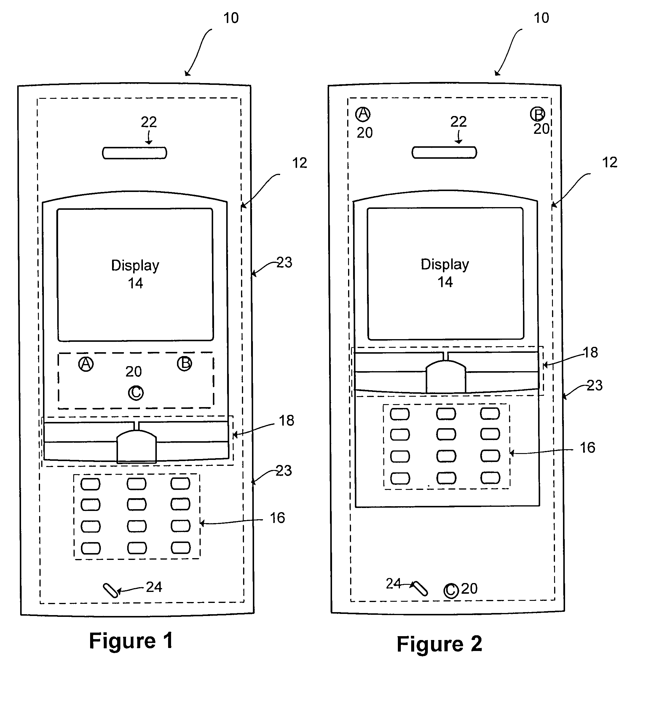
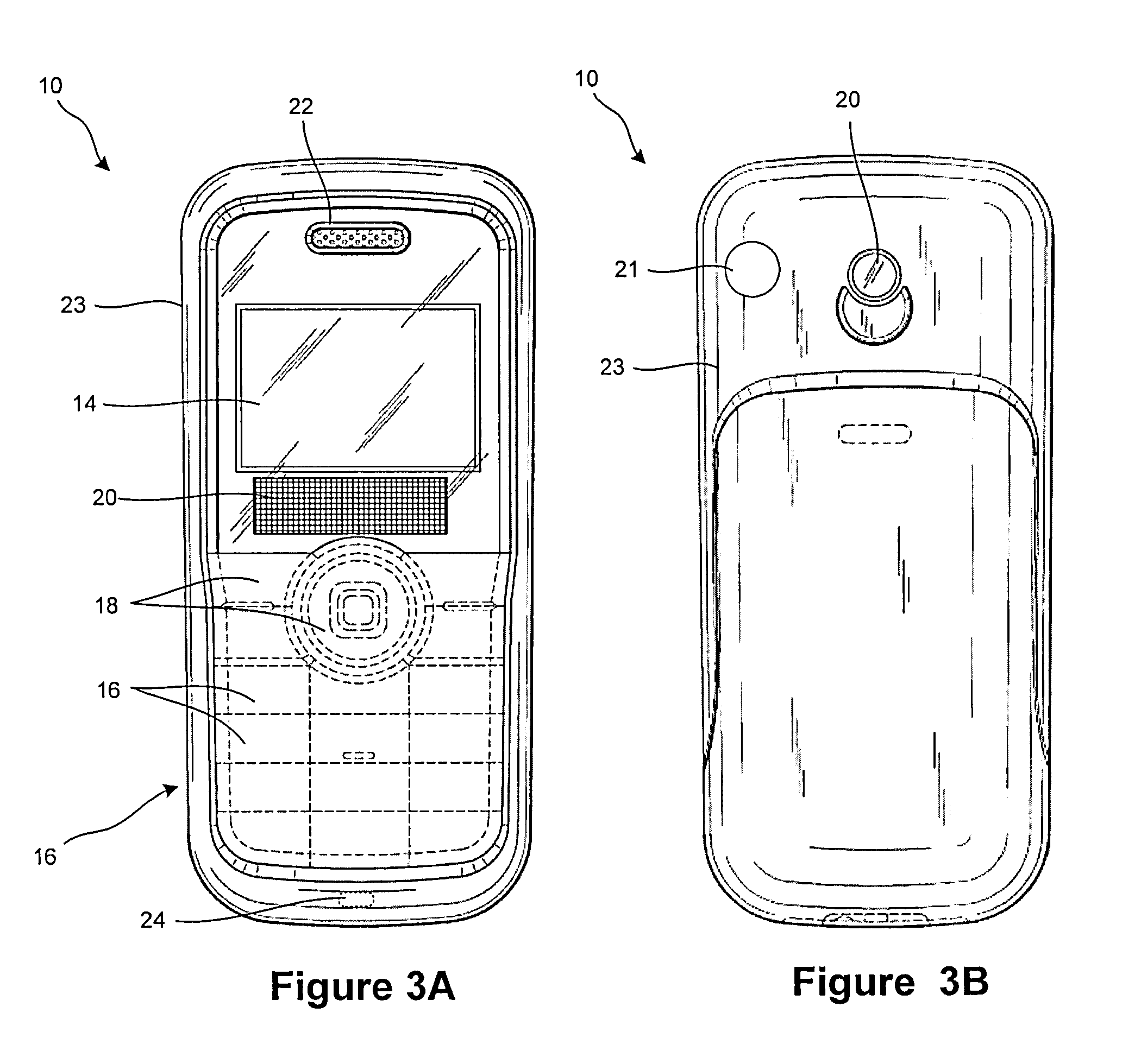
[0049]The present invention is directed to electronic equipment 10, sometimes referred to herein as an electronic device, communication device, mobile telephone, portable telephone, etc., having motion detection circuitry that is configured to detect motion and / or movement of an object near the electronic equipment and outputs a signal controlling one or more parameters associated with the electronic equipment and / or applications executed by the electronic equipment based at least in part on the detected movement of the object. The output signal is generally indicative of a location, movement, velocity and / or acceleration of the object in relation the movement detection circuitry and is generated without the object necessarily touching the electronic equipment and / or the movement detection circuitry. The movement detection circuitry may be used by an associated user to control one or more features of the electronic equipment and / or applications being executed on the electronic equip...


PUM


Abstract

A system, method and computer application for electronic device 10 for detecting movement near an electronic device. The electronic device includes movement detection circuitry configured to detect movement of an object near the movement detection circuitry. The movement detection circuitry includes at least one sensor that detects movement and generates at least one output signal corresponding to a position of the object detected. The electronic device further includes a memory for storing one or more predefined state parameters that correspond to one or more predefined movements to be detected by the movement detection circuitry. During processing, the output signals of the sensors are processed by averaging signals received from the one or more sensors to determine vertical movement above the movement detection circuitry and a determination is made as to whether the output signals of the one or more sensors are active or inactive to determine horizontal movement across the movement detection circuitry.

Description

RELATED APPLICATION DATA[0001]This application claims the benefit of U.S. Provisional Patent Application Ser. No. 60 / 914,844, filed Apr. 30, 2007, the entire disclosure of which is hereby incorporated by reference.TECHNICAL FIELD OF THE INVENTION[0002]The present invention relates to a method and algorithm for use in a contact-less user interface for electronic equipment that is capable of detecting movement of an object and controlling one or more parameters associated with the electronic equipment and / or applications executed by the electronic equipment based at least in part on the detected movement of the object.DESCRIPTION OF THE RELATED ART[0003]Electronic equipment, such as, for example, communication devices, mobile phones, personal digital assistants, etc. are typically equipped to communicate over cellular telephone communication networks. Such electronic equipment generally includes one or more user input devices. Common input devices include, for example, a computer mous...

Claims


Application Information

Patent Timeline
IPC IPC(8): G08B21/00
CPCG06F3/017G06F3/0304
Inventor MIDHOLT, MAGNUSSTALA, MICHAL
Owner SONY ERICSSON MOBILE COMM AB
Learn More