
Touchscreen for detecting multiple touches

a technology of touch screen and touch, applied in the field of touch screen, can solve the problems of ambiguity still exists in current saw and ir touch technology, single erroneous touch coordinate, and inability to produce reliable results

Active Publication Date: 2008-10-30
ELO TOUCH SOLUTIONS INC
View PDF19 Cites 183 Cited by
  • Summary
  • Abstract
  • Description
  • Claims
  • Application Information

AI Technical Summary

Benefits of technology

The patent describes a touchscreen system that uses multiple beams to detect touch on the screen. The system includes a transmitter that sends beams in one direction, a beam splitter that splits the beams into two or three directions, and a receiver that receives the beams. This system can detect multiple touches on the screen simultaneously. The technical effect of this patent is to provide a more accurate and efficient way to detect touch on a touchscreen system.

Problems solved by technology

Some touch technologies, such as most resistive and capacitive touchscreens, may produce a single erroneous touch coordinate when subjected to simultaneous multiple touches.
SAW and IR touchscreens are therefore promising for multiple-touch applications, however, some ambiguity still exists in current SAW and IR touch technologies.
The processor may attempt to determine which coordinates should be paired based on graphics that were displayed at the time or by using other factors, such as a time of a lift-off event, but unfortunately these methods do not always produce reliable results.
Some current technology, such as some IR touchscreen designs using slightly non-parallel IR beams, may be able to discern multiple touches that are widely separated from each other, but are not able to discern multiple touches that occur in closer proximity to one another.
Unfortunately, known XYU touchscreen technology also has its limitations.
To date, XYU touchscreen technology has not been applied to IR touchscreen designs because the narrow light emitting diode (LED) emission cone angle and the narrow phototransistor reception cone angle are incompatible with the common opto-electronic components being used for both X / Y and U beams.
Also, additional transmit and receive U arrays require scattering by U array reflectors at angles significantly larger than 90 degrees, for which SAW scattering may be inefficient.
This contributes to weak signals and acoustic parasites.
The seal may absorb some of the acoustic energy, and it is not allowable to place a seal on top of an array.
The seal may thus increase the overall size of the touchscreen or minimize the usable touch area of the touchscreen, both of which are undesirable.

Method used


Image

  • Touchscreen for detecting multiple touches
  • Touchscreen for detecting multiple touches
  • Touchscreen for detecting multiple touches

Examples


Embodiment Construction

[0041]The foregoing summary, as well as the following detailed description of certain embodiments of the present invention, will be better understood when read in conjunction with the appended drawings. To the extent that the figures illustrate diagrams of the functional blocks of various embodiments, the functional blocks are not necessarily indicative of the division between hardware circuitry. Thus, for example, one or more of the functional blocks (e.g., processors or memories) may be implemented in a single piece of hardware (e.g., a general purpose signal processor or random access memory, hard disk, or the like). Similarly, the programs may be stand alone programs, may be incorporated as subroutines in an operating system, may be functions in an installed software package, and the like. It should be understood that the various embodiments are not limited to the arrangements and instrumentality shown in the drawings.

[0042]FIG. 1 illustrates a touch display 100 formed in accord...


PUM


Abstract

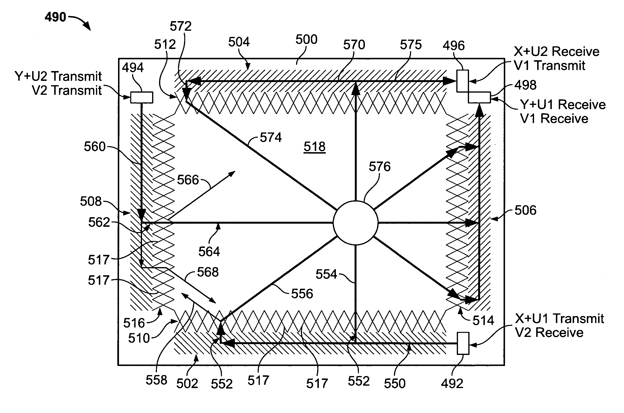
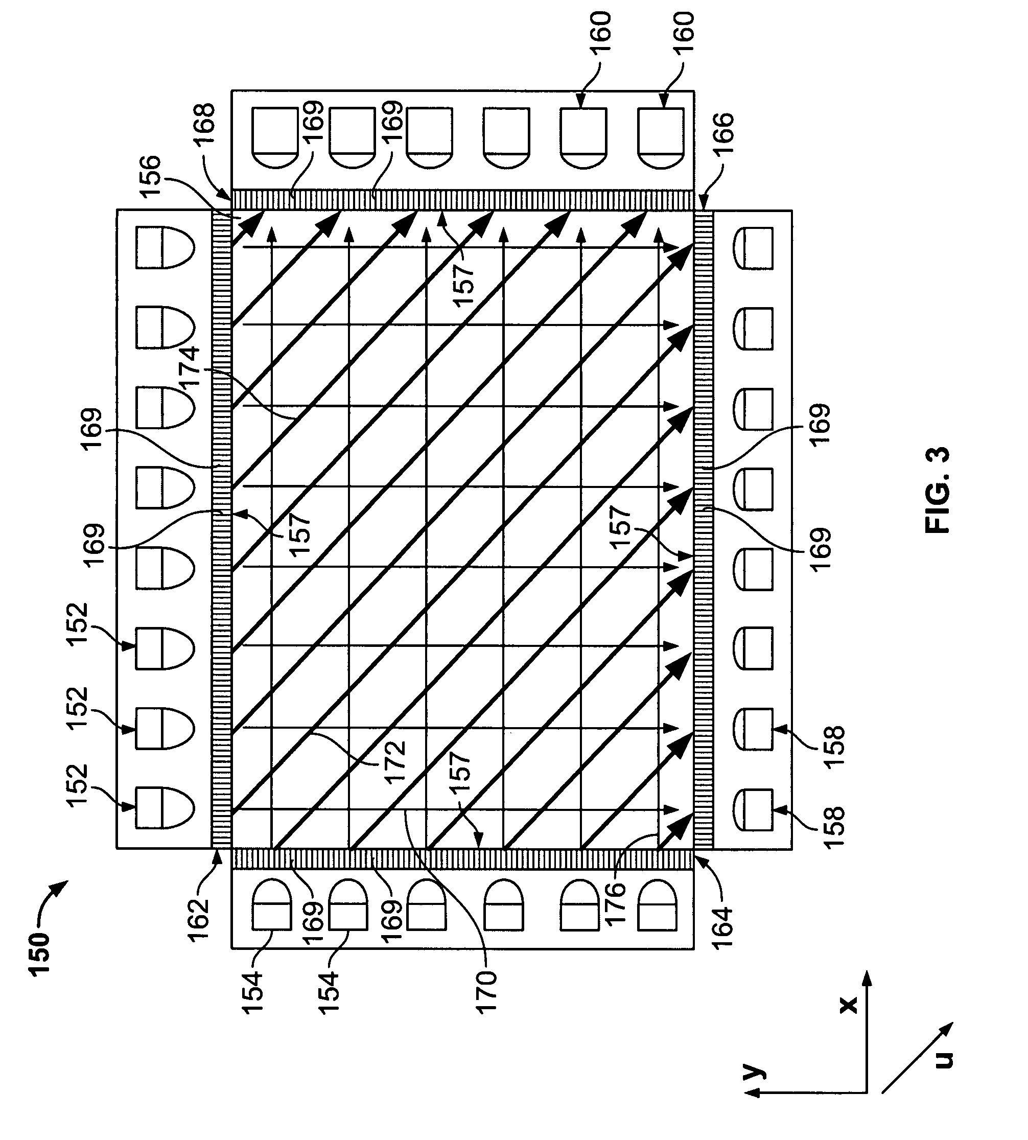
A touchscreen system comprises a touch area. At least one transmitter is positioned proximate to outer edges of the touch area for transmitting first beams in a first direction. At least one beam splitter is positioned proximate to the outer edges of the touch area for splitting the first beams into at least second and third beams that travel through the touch area in at least second and third directions, respectively. The at least one beam splitter comprises a plurality of deflecting elements. Receivers are positioned proximate to the outer edges of the touch area for receiving the at least second and third beams.

Description

BACKGROUND OF THE INVENTION[0001]This invention relates generally to touchscreens, and more particularly, to touchscreens used to detect multiple touches.[0002]Applications that have a need or requirement for sensing multiple touches are becoming more popular. For example, applications that use graphical interfaces to input information such as by displaying a standard keyboard on the screen may rely on a user selecting two keys at the same time, such as a shift key to make an upper-case character selection. Also, as screens become smaller, selecting multiple graphics at the same time may be desirable to provide input capability to a user within the smaller touchscreen footprint. Gaming and other multi-user applications also increase the need for detecting touches from two or more users interacting with the same touchscreen at the same time.[0003]Some touch technologies, such as most resistive and capacitive touchscreens, may produce a single erroneous touch coordinate when subjected...

Claims


Application Information

Patent Timeline
Patent Type & Authority Applications(United States)
IPC IPC(8): G06F3/041
CPCG06F3/0436G06F3/0421G06F2203/04104
Inventor KENT, JOEL C.AROYAN, JAMES L.GAO, TINGTANAKA, YOSHIKAZUSCHARFF, DANIEL H.
Owner ELO TOUCH SOLUTIONS INC
Learn More