Method and apparatus for locating and measuring the distance to a target

a distance measurement and laser technology, applied in the field of lasers, can solve the problems of difficult to see the laser spot, measurement errors, and inability to view the laser spot in bright sunlight and at longer distances

Inactive Publication Date: 2008-10-30
ROBERT BOSCH CO LTD
View PDF18 Cites 34 Cited by
  • Summary
  • Abstract
  • Description
  • Claims
  • Application Information

AI Technical Summary

Benefits of technology

[0006]Another embodiment comprises an apparatus for finding a target and measuring the distance to the target that comprises a protective housing, a camera module in the housing, a lens mounted in a front end portion of the housing, and a light path through the lens, a first display in the housing operatively connected to the camera module for receiving the image data and providing a visual display of the image, an image sensor, an electronic memory for selectively storing data of images from the image sensor, control circuitry for controlling the image sensor and electronic memory to selectively acquire image data of a scene and store the same, a laser distance finder in the housing configured to direct a laser beam toward the scene and generate data that is indicative of the distance to a target in the scene, a second display in the housing operatively connected to the distance finder for displaying distance data, and a switch for storing image data in the memory.

Problems solved by technology

While there is generally no difficulty in seeing where the laser spot impinges on a surface when used indoors, the ability to view a laser spot can be severely compromised in bright sunlight and at longer distances.
Even with these aids, it is often difficult to see the laser spot.
For example, a user may want to measure the distance to a narrow column that may be several yards in front of a wall, so if the user is intending to measure the distance to the column and is actually measuring the distance to the wall, a few degrees of misalignment can result in measurement errors that can have significant adverse consequences.
Even when the measurements are correct for the intended target, it can be cumbersome to provide an accurate record and description of a series of measurements.

Method used


Image

  • Method and apparatus for locating and measuring the distance to a target
  • Method and apparatus for locating and measuring the distance to a target
  • Method and apparatus for locating and measuring the distance to a target

Examples


Embodiment Construction

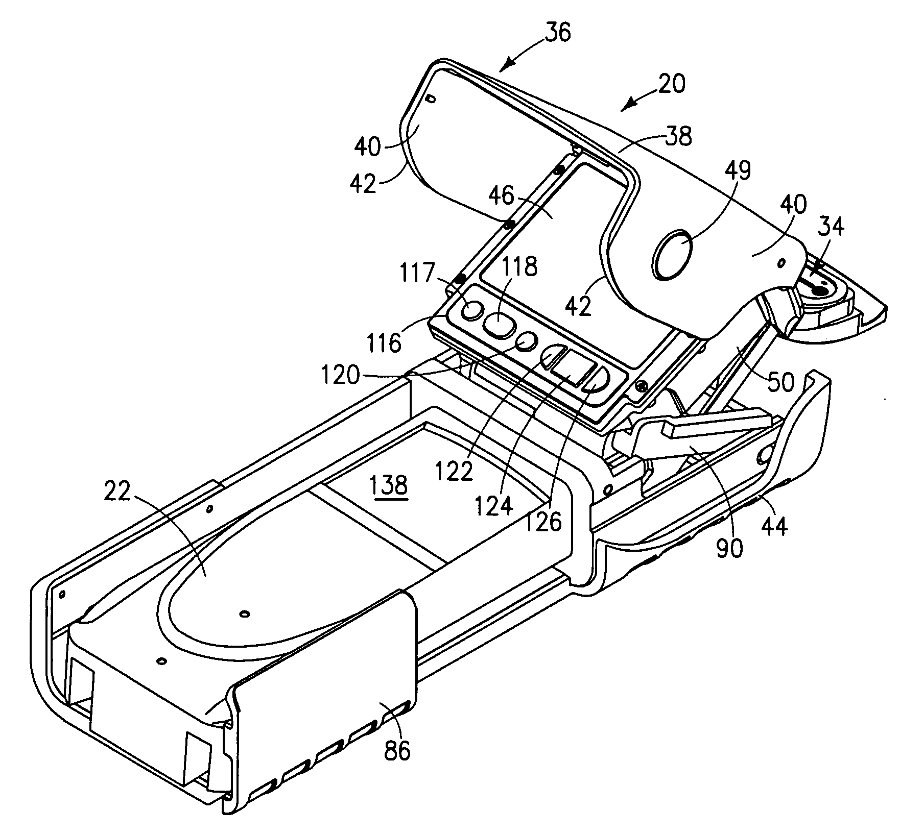
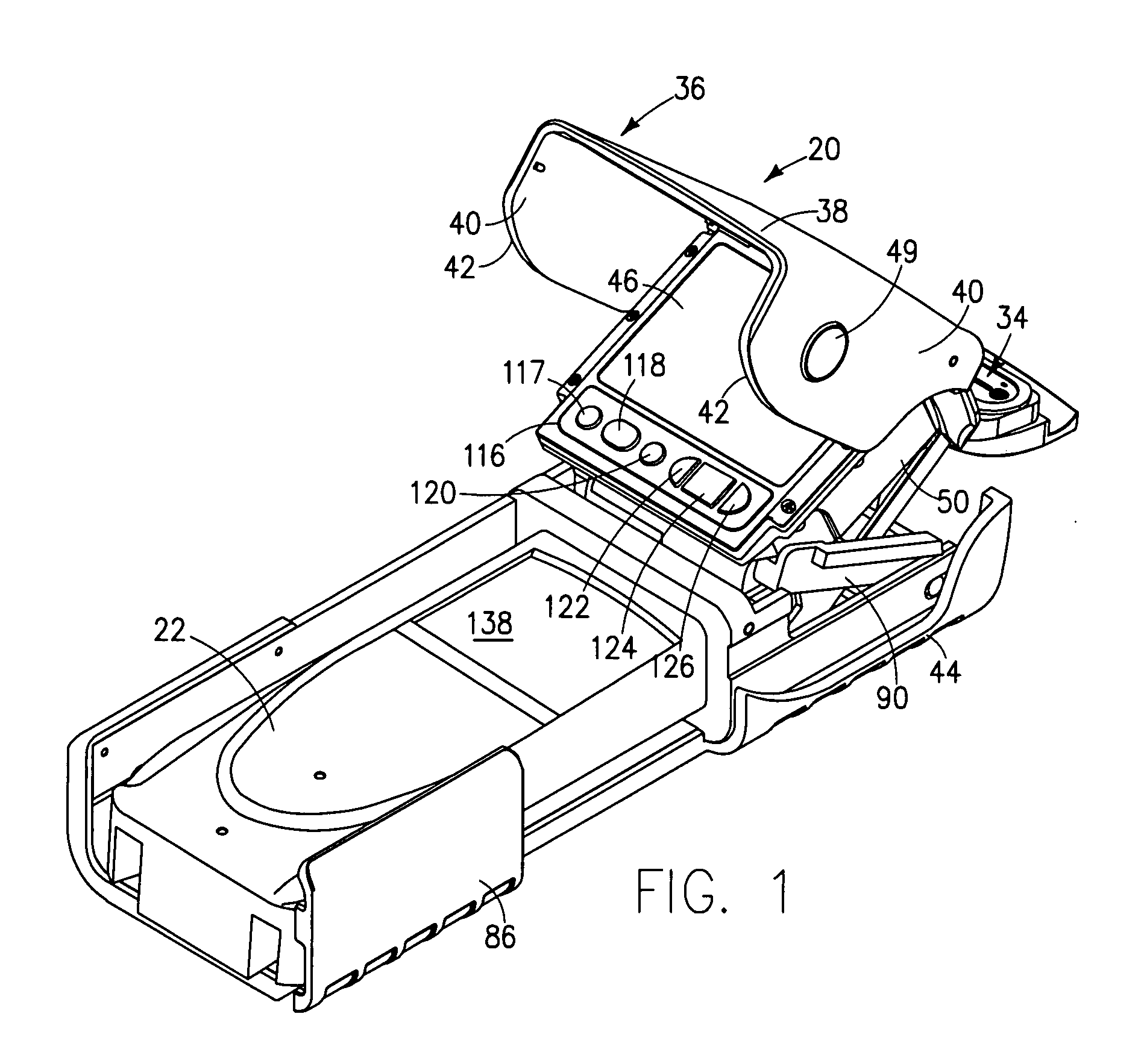
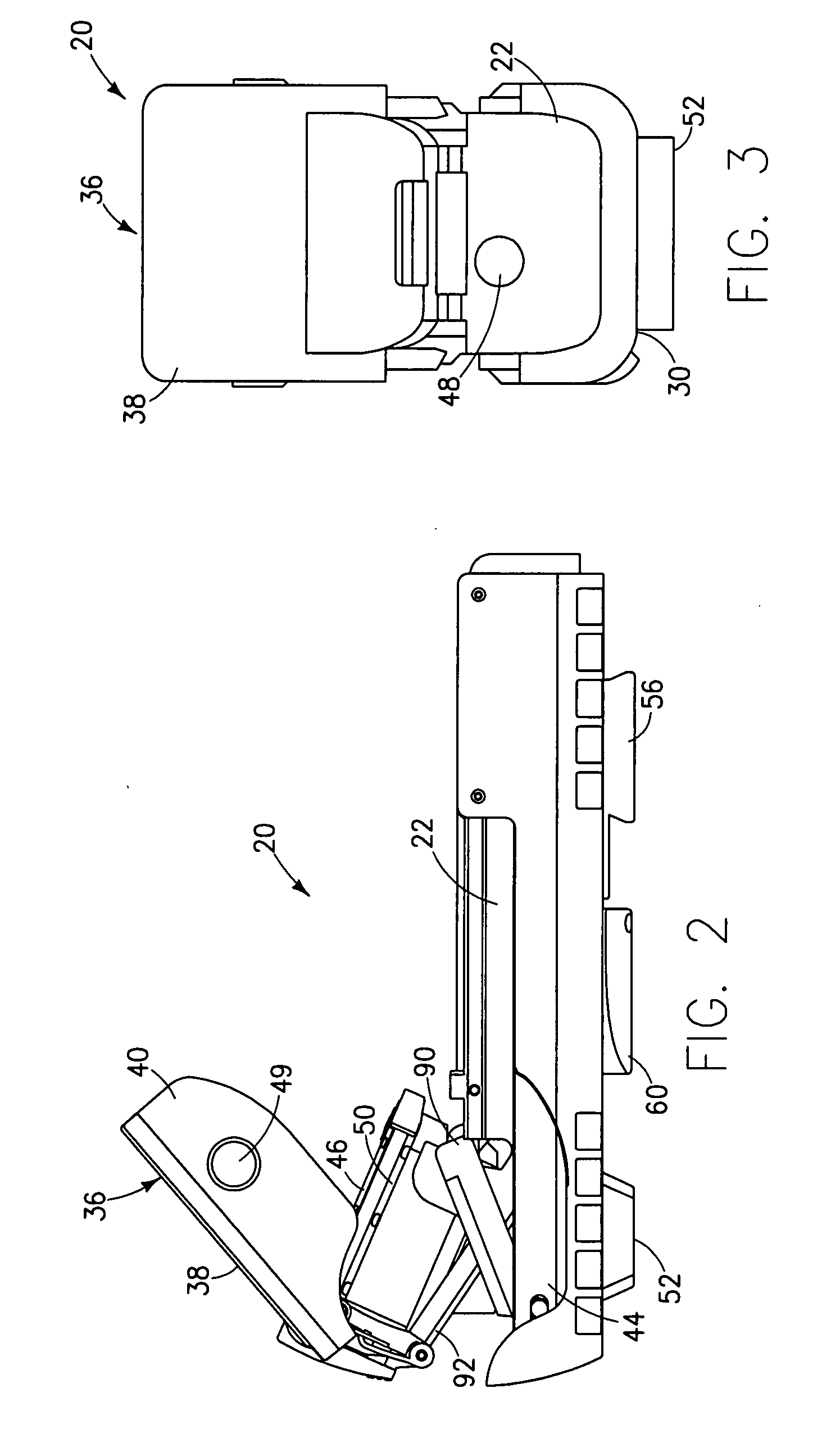
[0027]Broadly stated, preferred embodiments of the present invention are directed to a target finding apparatus (hereinafter referred to as a target finder) as well as a method of locating targets, measuring the distance to the targets and merging video images together with measurement data to provide a reliable record of such activity. It should be understood that the target finder is preferably used with a laser measurement device or range finder that has a compact design, preferably configured to be small enough to be held in the palm of one's hand, such as the RoboToolz Model RT-9000 RoboTape® laser distance measure device. Similarly, the DISTO™ range finders that are marketed under the Leica® brand can be used together with embodiments of the target finder described herein.

[0028]It should be understood that while the target finder may be marketed separately for use with either the RoboTape® range finder or the Leica® DISTO™ range finders, it should be understood that other embo...


PUM


Abstract

Embodiments of the invention comprise an apparatus for use with a laser range finder configured to direct a laser beam toward a scene to measure the distance to a target in the scene and having a range finder display for displaying data, including data that is indicative of the distance to a target, wherein the apparatus comprises a protective housing, a camera module in the housing, the camera module including a lens mounted in a front end portion of the housing, and a light path through the lens to image sensor, an image sensor operatively connected to the camera module for receiving images acquired by the camera module, electronic memory for selectively storing data of images from the image sensor, circuitry for controlling the operation of the image sensor and the memory, a camera display in the housing operatively connected to the image sensor for receiving the image data and providing a visual display of the image, and a switch for storing image data in the memory. Other embodiments include a projector in the housing for projecting the data displayed by the second display onto the image sensor to thereby capture the image data of the scene and displayed distance data together.

Description

BACKGROUND OF THE INVENTION[0001]The present invention generally relates to the use of lasers for measuring distances to a target.[0002]It is common practice to use laser range finders to determine distances to a target that may be close or several hundred yards. The laser range finders are generally of two types, one of which is a phase shifting electronic measurement while the other measures the elapsed time for a signal to be propagated, reflected and detected. A common feature of either type of operation is the use of a laser beam directed to the target so that the user knows what precise target for which distance is being measured. While there is generally no difficulty in seeing where the laser spot impinges on a surface when used indoors, the ability to view a laser spot can be severely compromised in bright sunlight and at longer distances.[0003]Some range finder users wear red colored eye glasses that can aid one to see the red laser spot in bright light conditions, while o...

Claims


Application Information

Patent Timeline
Patent Type & Authority Applications(United States)
IPC IPC(8): G01C3/08H04N9/73G01S17/86
CPCG01S7/4813G01S17/023G01S17/08G01S17/86
Inventor YUNG, WAI LAMBITTNER, WILFRIED ALOIS ANTONLAM, YAT WAHCHAN, SAI CHAKCHAN, WAH PONGNG, KWONG LAMZIMMERMAN, THOMAS PAUL RICHARD
Owner ROBERT BOSCH CO LTD
Why Eureka
Try Eureka