
Label producing apparatus

a technology of labeling and producing apparatus, which is applied in the direction of typewriters, digital output to print units, instruments, etc., can solve the problems that the above-described prior art does not particularly take into account such a reduction in and achieve the effect of reducing the labor burden of operators and simplifying the reading operation

Inactive Publication Date: 2008-10-30
BROTHER KOGYO KK
View PDF7 Cites 12 Cited by
  • Summary
  • Abstract
  • Description
  • Claims
  • Application Information

AI Technical Summary

Benefits of technology

[0009]It is therefore an object of the present disclosure to provide a label producing apparatus capable of reducing the labor burden of the operator when the operator is to provide operation instructions to a device for working.
[0011]In the label producing apparatus according to the present aspect, not only the wired-type first command input part but also the wireless-type second command input part are provided as command input part configured to input command signals for providing operation instructions to devices for working. As a result, it is possible to prepare each of the RFID tags corresponding to the various second command signals, for example, and input the second command signal from the second command input part using the RFID tag corresponding to the command content of the desired operation instructions. With this arrangement, compared to a case where the first command input part inputs a first command signal generated from a complex operation performed using a wired operation terminal, for example, the same result is accomplished by a much simpler operation of reading the RFID tag. That is, the present disclosure does not require the operator to perform a complex operation using the keys, buttons, and switches of the operation terminal in order to generate a command signal, thereby reducing the operation labor of the operator.

Problems solved by technology

Nevertheless, the above-described prior art does not particularly take into consideration such a reduction in the labor burden of the operator.

Method used


Image

  • Label producing apparatus
  • Label producing apparatus
  • Label producing apparatus

Examples


embodiment 1

[0094]The following describes embodiment 1 of the present disclosure with reference to accompanying drawings.

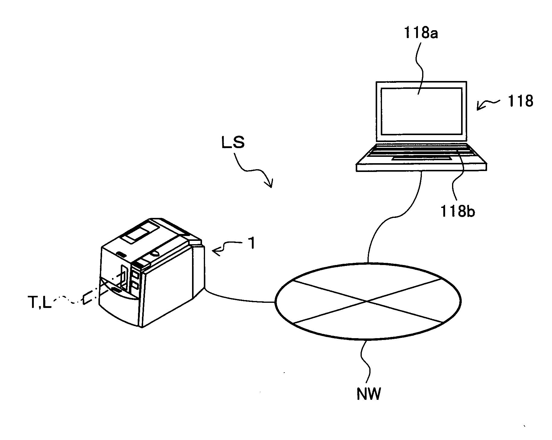
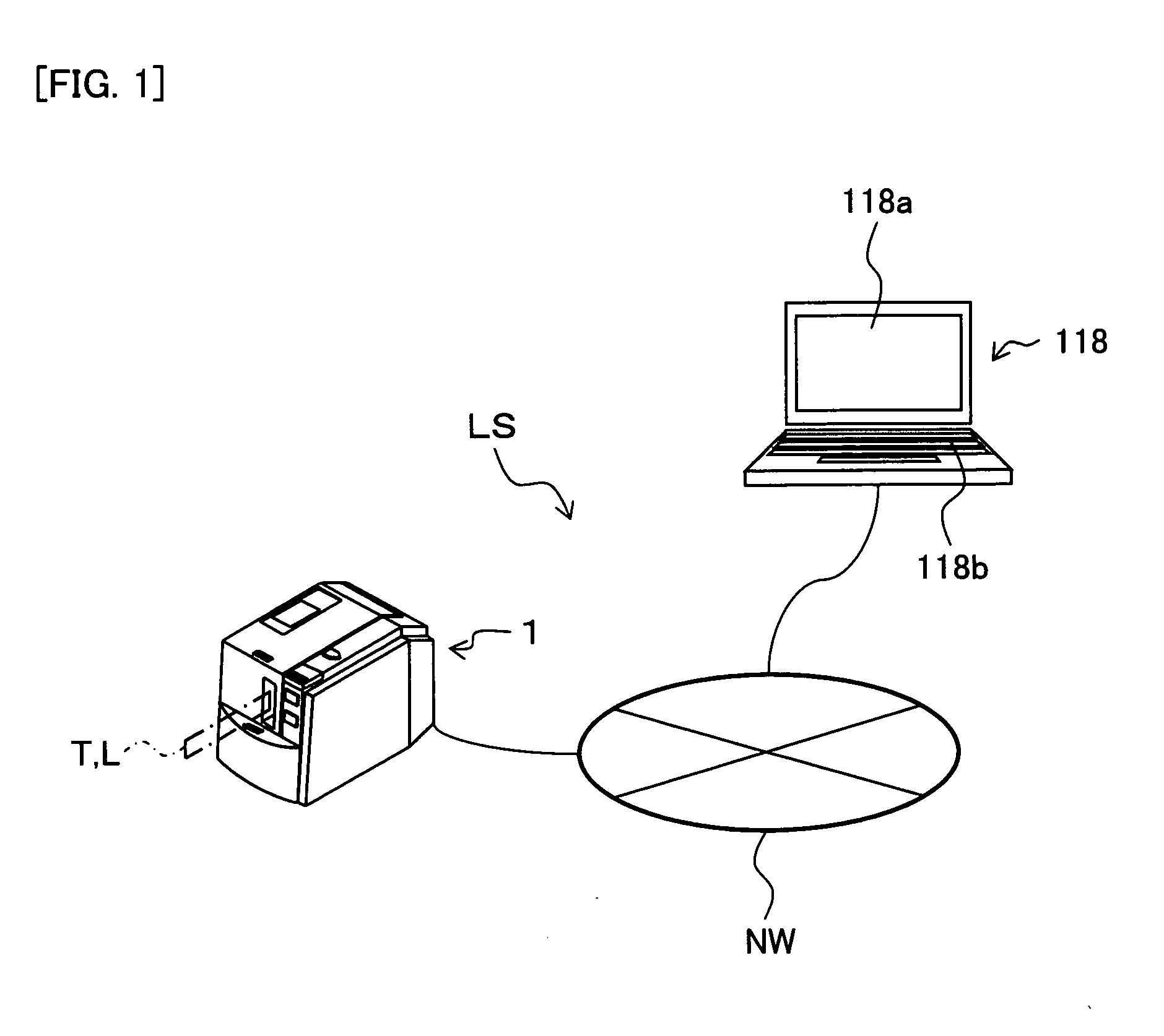
[0095]In the label manufacturing system LS shown in FIG. 1, a label producing apparatus 1 of the present embodiment is connected to a PC 118 via a wired or wireless communication line NW. The PC 118 comprises a display part 118a such as a liquid crystal display, and an operation part 118b such as a keyboard and mouse, making it possible to edit the print content when producing a label (i.e., a label with print; that is, an RFID label T or regular label L) using the label producing apparatus 1.

embodiment 6

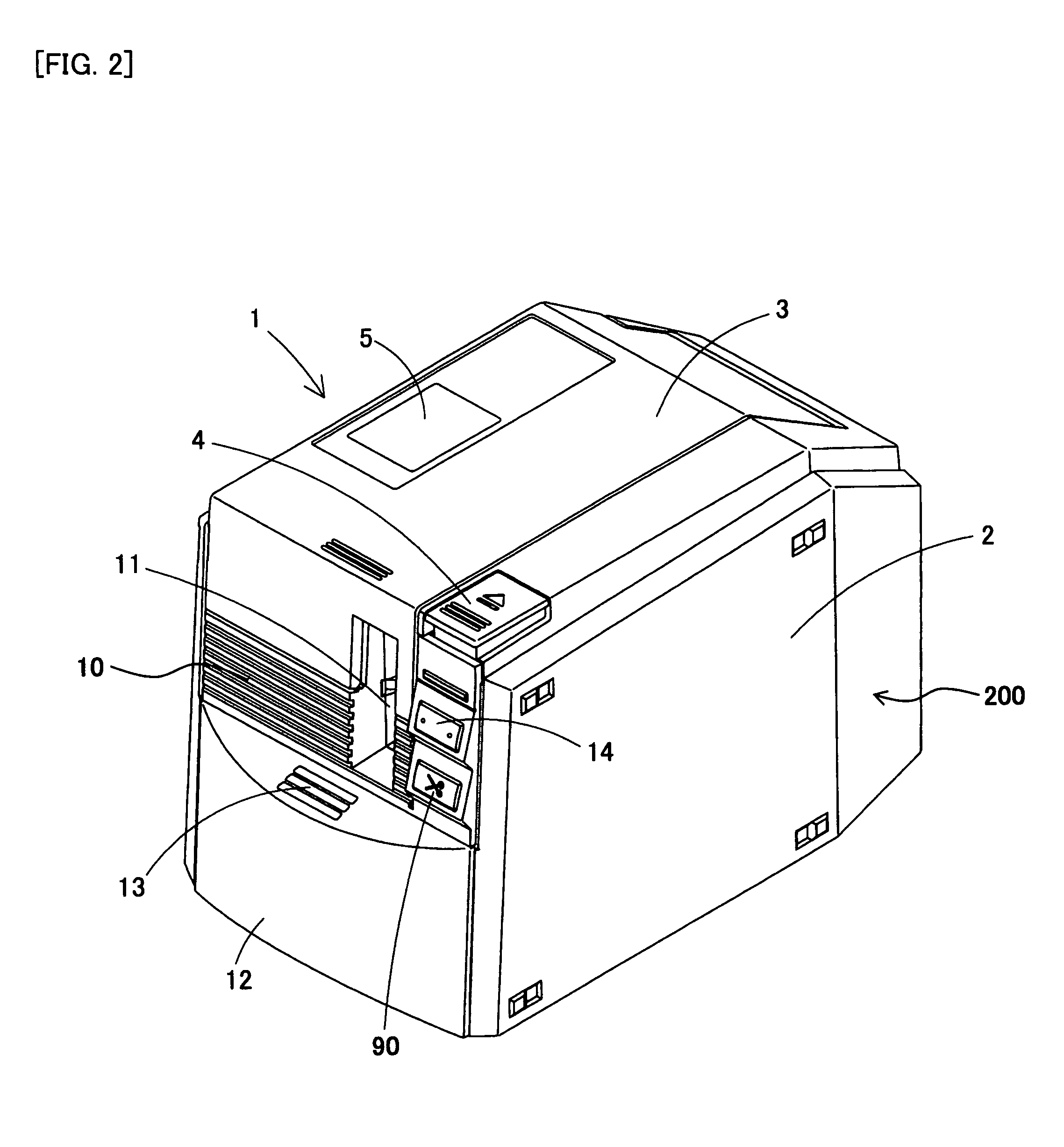
[0096]The label producing apparatus 1, as shown in FIG. 2, produces an RFID label T with print using a base tape comprising an RFID circuit element To (hereinafter, suitably referred to as “RFID circuit element To for label production”) in the apparatus, produces a regular label L using an regular base tape not comprising an RFID circuit element To, and reads (acquires) information from the RFID circuit element To (hereinafter suitably referred to as “RFID circuit element To for information acquisition”) from outside the apparatus, based on the operation from the PC 118. The RFID information read function from outside this apparatus will be described in detail in embodiment 6 described later.

[0097]The label producing apparatus 1 comprises an apparatus main body 2 having a housing 200 of a substantially six-sided (substantially cubical) shape, and an opening / closing lid 3 provided on the upper surface of the apparatus main body 2 so as to freely open and close (or detach).

[0098]The h...

embodiment 2

[0277]The following describes embodiment 2 of the present disclosure with reference to accompanying drawings.

[0278]The configurations of the label manufacturing system LS of the present embodiment and the PC 118 and label producing apparatus 1 thereof are the same as those of the above embodiment 1, and detailed descriptions thereof will be omitted.

[0279]The content shown in FIG. 29 is executed by a control circuit 130A (not shown) of the PC 118 when the RFID label T is produced using the label manufacturing system LS of the present embodiment. Note that the control circuit 130A starts this flow when, for example, the operator enters a suitable operation that instructs the system to start tag label editing.

[0280]In FIG. 29, Step S510 to step S520 are the same as step S10 to step S20 of the aforementioned FIG. 8. In these steps, the decision is made as to whether or not the cartridge information detected by the cartridge sensor 81 of the label producing apparatus 1 and acquired by th...


PUM


Abstract

This disclosure discloses a label producing apparatus that produces a label with print, comprising: a feeding device that feeds a print-receiving tape or a base tape thereto; a printing device that performs printing on the print-receiving tape; a first command input part that inputs a first command signal for providing instructions from an external source; a second command input part that inputs a second command signal from an external source; and a control portion that controls said at least one of devices for working based on the first or second command signal.

Description

CROSS-REFERENCE TO RELATED APPLICATIONS[0001]This application claims priority from JP 2007-118855, filed Apr. 27, 2007, the contents of which are hereby incorporated by reference.BACKGROUND[0002]1. Field[0003]The present disclosure relates to a label producing apparatus for producing a label with print to be affixed to a target object.[0004]2. Description of the Related Art[0005]In prior arts, a label producing apparatus configured to store a tape within a cartridge in the form of a roll and print desired text on the tape while the tape is fed out from the roll so as to produce a label has already been proposed (refer to JP, A, 2005-254566, Paragraph [0100], FIG. 1, for example).[0006]In this prior art, the label producing apparatus comprises a roll around which a base tape comprising a separation sheet is wound, and a roll around which a print-receiving tape (cover film) to be bonded to this base tape is wound. The base tape and the print-receiving tape are respectively fed out fro...

Claims


Application Information

Patent Timeline
Patent Type & Authority Applications(United States)
IPC IPC(8): G06F3/12
CPCB41J3/4075
Inventor MORIYAMA, SATORUSUZUKI, MIKITOSHIIKEDO, TATSUHIROOSUKA, NORIYUKIYAMAGUCHI, KOSHIRO
Owner BROTHER KOGYO KK
Learn More