Cooling structure for power supply

a power supply and cooling structure technology, applied in the direction of electrical equipment, electrical apparatus, electrical apparatus contruction details, etc., can solve the problems of noisy cooling fan and inability to exhaust hot air outside the housing, and achieve the effect of reducing noise and easy exhaustion of hea

Inactive Publication Date: 2008-10-30
ENERMAX TECHNOLOGY CORPORATION
View PDF8 Cites 55 Cited by
  • Summary
  • Abstract
  • Description
  • Claims
  • Application Information

AI Technical Summary

Benefits of technology

[0006]One particular aspect of the present invention is to provide a cooling structure for a power supply. The cooling structure includes a plurality of cooling fins disposed slantwise, and there is an air-guiding channel between the cooling fins to guide the airflow of the cooli...

Problems solved by technology

Therefore, the hot air cannot be exhausted...

Method used


Image

  • Cooling structure for power supply
  • Cooling structure for power supply
  • Cooling structure for power supply

Examples


Embodiment Construction

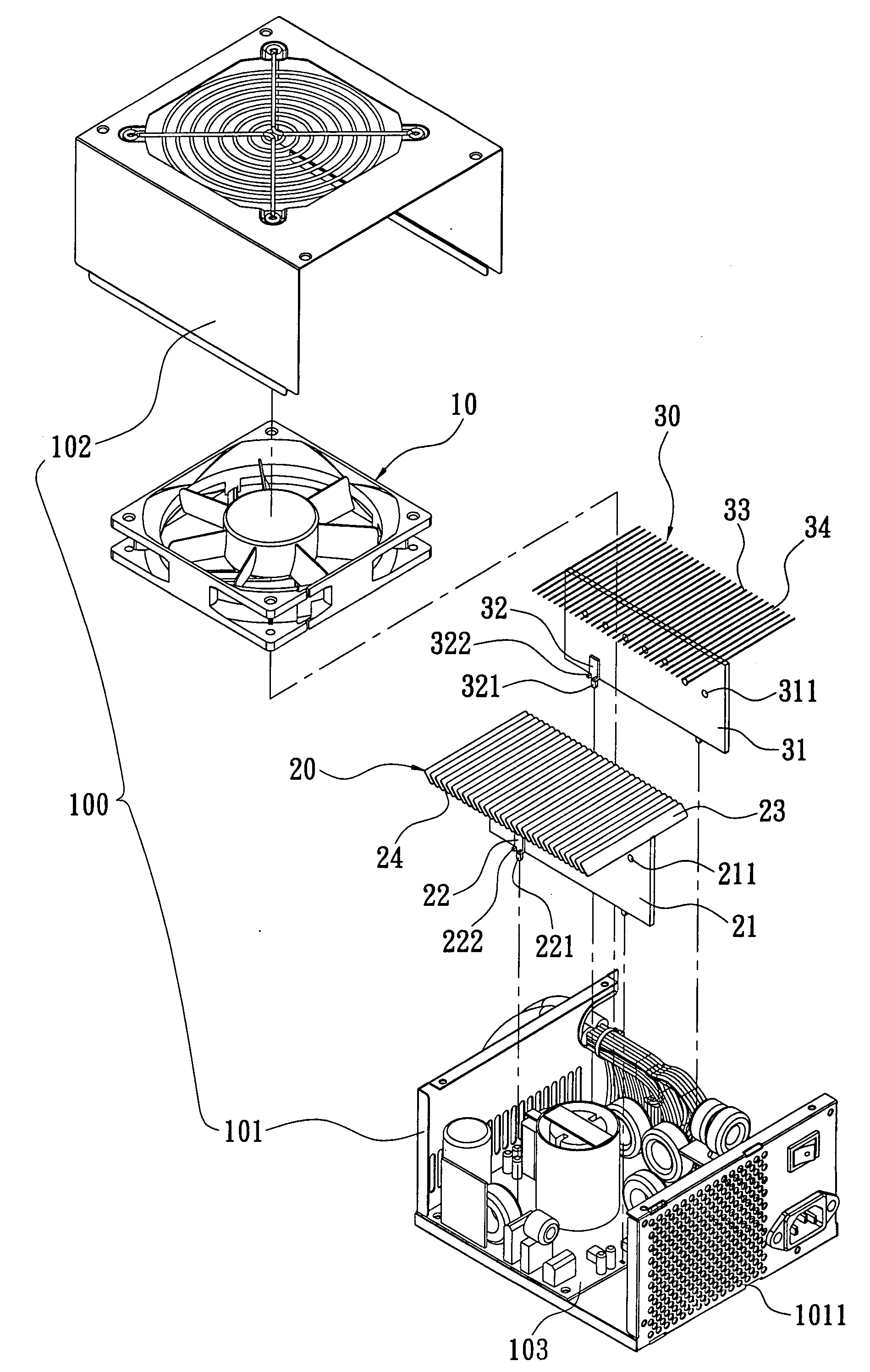
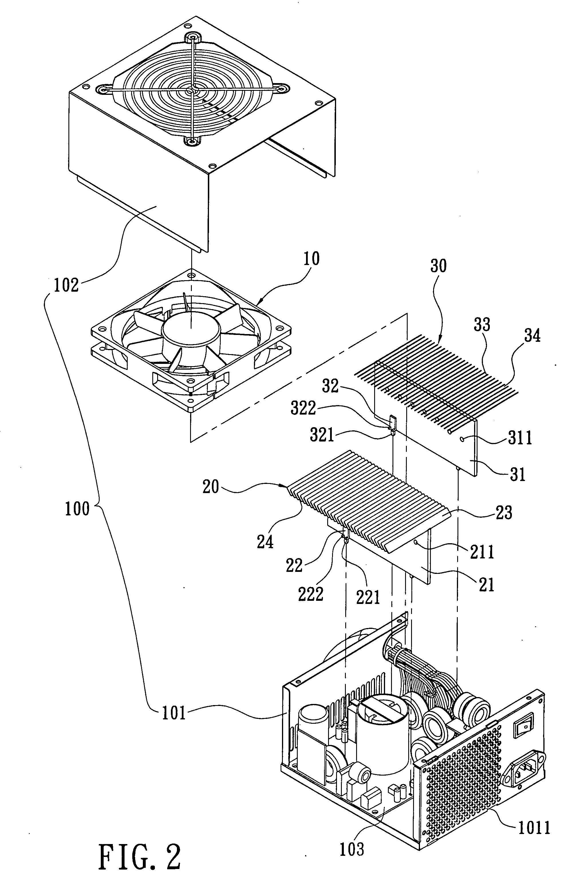
[0018]Reference is made to FIGS. 2˜4, which show the cooling structure for a power supply of the first embodiment of the present invention. The cooling structure is installed in a housing 100 of the power supply. The housing 100 includes a base 101, and a cover 102 that covers the base 101. On the front side surface of the base 101, there is a plurality of cooling holes 1011. In the interior of the base 101, there is a circuit board 103. The cooling structure includes a cooling fan 10, a first cooler 20, and a second cooler 30. The cooling fan 10 is located on an inner side of a top surface of the cover 102 of the housing 100 for guiding air into the housing 100 to exhaust heat.

[0019]The first cooler 20 includes a first vertical board 21, two first branching legs 22, and a plurality of first cooling fins 23. The first vertical board 21 is made of conductive metal material and is a rectangular board. The first vertical board 21 has a plurality of fastening holes 211. The fastening ho...


PUM


Abstract

A cooling structure for a power supply is disclosed. The power supply has a housing. The cooling structure includes a cooling fan and a cooler. The cooling fan is located on the inner side of the top surface of the housing. The cooler is located below the cooling fan. The cooler includes a vertical board and a plurality of cooling fins. The cooling fins are disposed slantwise on the vertical board and at intervals. There is a plurality of air-guiding channels between the cooling fins. Thereby, the airflow of the cooling fan can be guided forward to a specified direction. The hot air circulating flow will not occur. The cooling fan blows onto the electronic elements on the circuit board to exhaust the heat generated by the electronic elements, and noise generated from the cooling fans is lowered.

Description

BACKGROUND OF THE INVENTION[0001]1. Field of the Invention[0002]The present invention relates to a cooling structure for a power supply. In particular, this invention relates to a cooling structure that includes a plurality of cooling fins disposed slantwise. There is also an air-guiding channel between the cooling fins.[0003]2. Description of the Related Art[0004]In order to provide the required power for a computer, a power supply is usually installed in the computer. A cooling fan is located on the top of the housing of the power supply, and there is a circuit board located in the housing of the power supply. The circuit board is located below the cooling fan and is disposed with a plurality of chips. On the circuit board, there is a cooler. As shown in FIG. 1, the cooler 1a includes a main board 10a, and two branching legs 20a. On a top surface of the main board 10a, there is a plurality of cooling fins 11a that are vertical and disposed at intervals. The two branching legs 20a ...

Claims


Application Information

Patent Timeline
IPC IPC(8): H05K7/20
CPCH05K7/20909
Inventor LEE, JIA-SHIUNN
Owner ENERMAX TECHNOLOGY CORPORATION
Why Eureka
Try Eureka