Permanent magnet electro-mechanical device providing motor/generator functions

a permanent magnet, electromechanical technology, applied in the direction of dynamo-electric machines, electrical devices, dc commutators, etc., can solve the problems of reducing the efficiency of operation when the motor is producing peak power, introducing high cogging torque at start-up, and inability to turn off permanent magnets

Inactive Publication Date: 2008-11-06
QM POWER
View PDF21 Cites 73 Cited by
  • Summary
  • Abstract
  • Description
  • Claims
  • Application Information

AI Technical Summary

Benefits of technology

This patent is about a device that can act as a motor or generator using permanent magnets. It has control coils and a rotor, and the arrangement of the magnets is designed to optimize performance. The device can control the magnetic flux and produce power when the rotor is turned. The technical effect is a more efficient and effective device for generating motion or power.

Problems solved by technology

The technical problem addressed in this patent text relates to improving the efficiency of permanet magnet motors during peak power production without adding significant size and weight to the motor.

Method used


Image

  • Permanent magnet electro-mechanical device providing motor/generator functions
  • Permanent magnet electro-mechanical device providing motor/generator functions
  • Permanent magnet electro-mechanical device providing motor/generator functions

Examples


Embodiment Construction

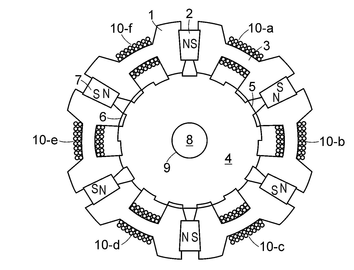
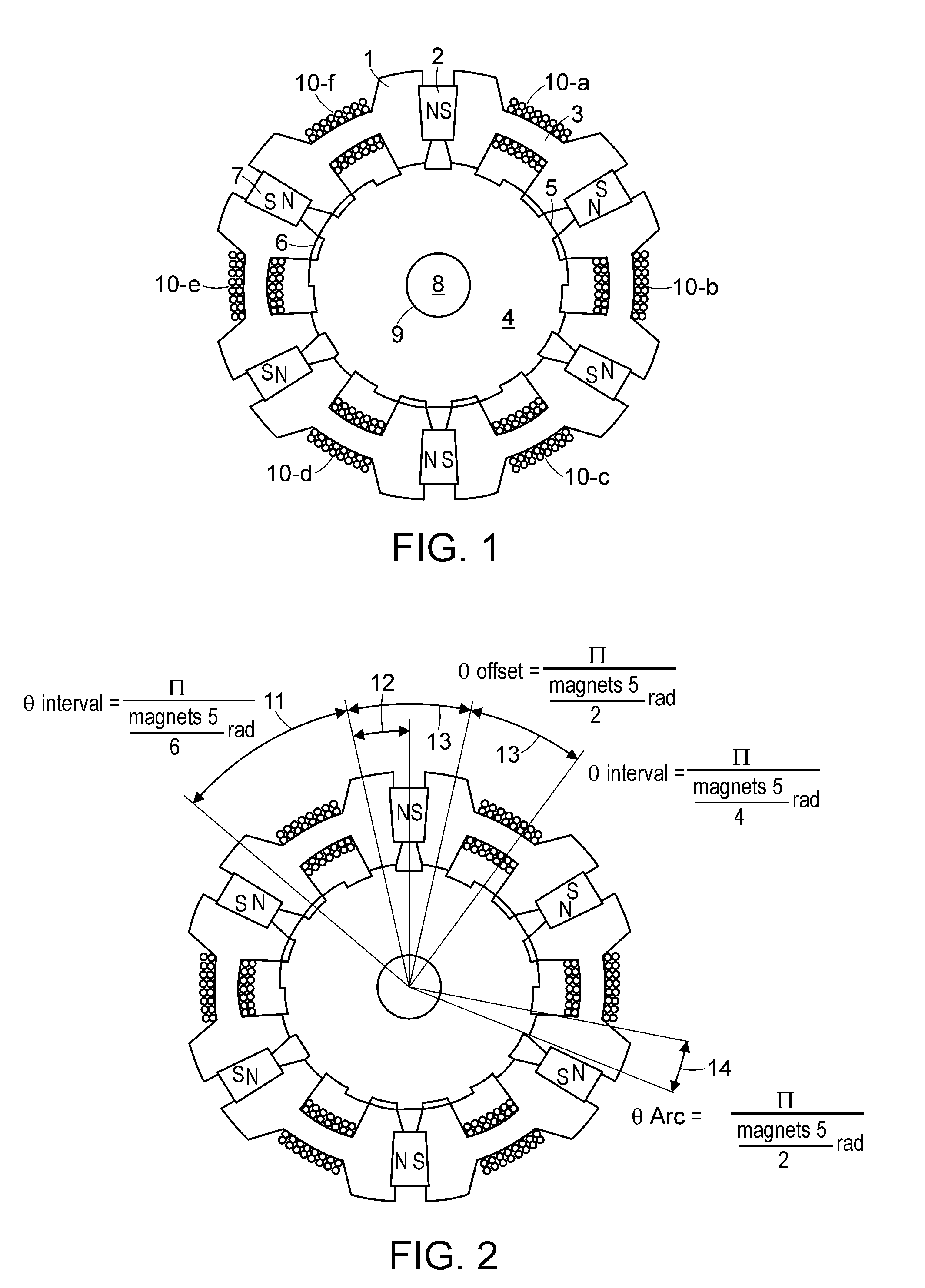
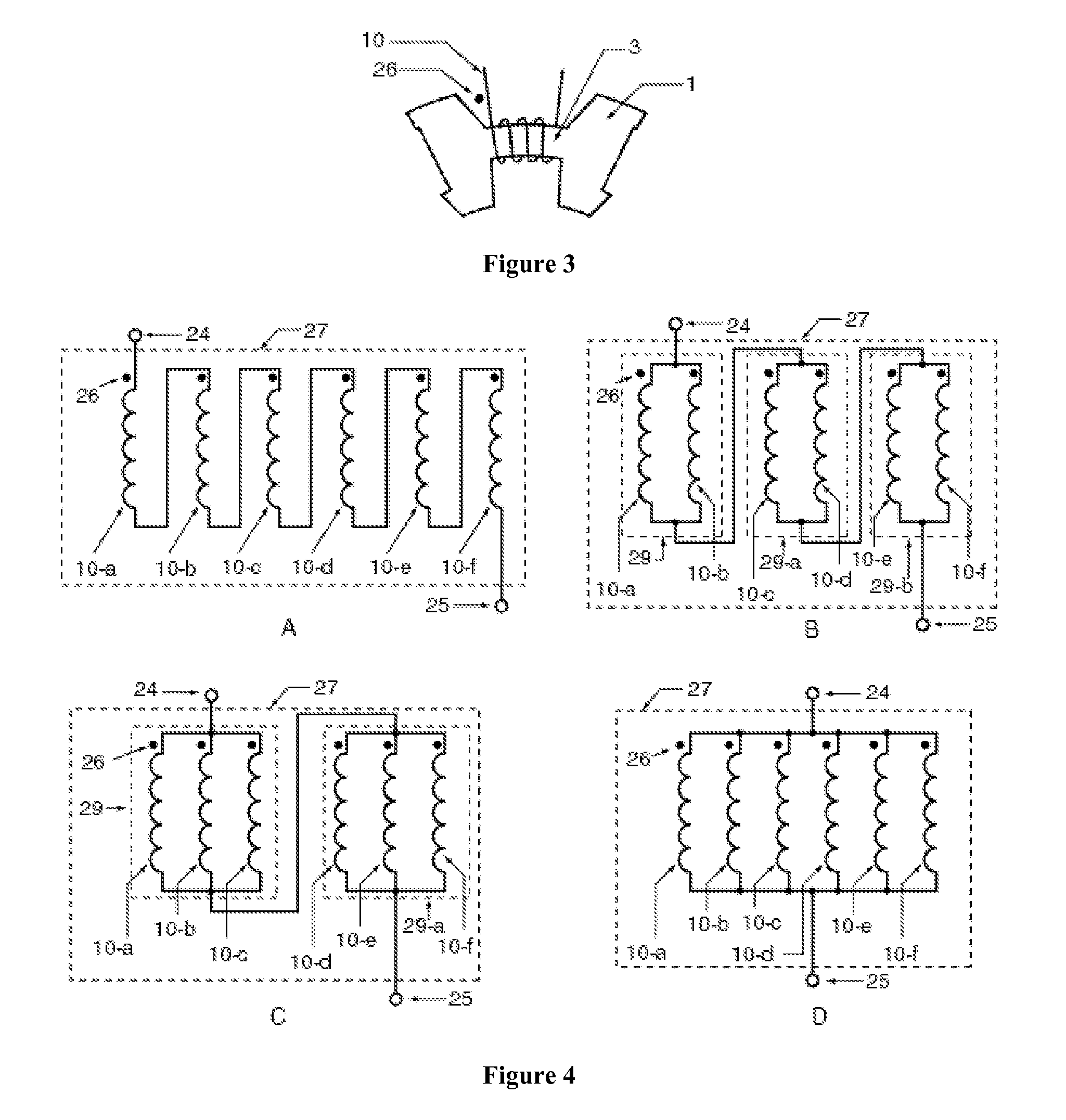
[0049]An apparatus, method and means for providing a permanent magnet electro-mechanical device that functions as a motor or generator are disclosed. The electro-mechanical device includes control coils, a rotor, and uses an angular arrangement of permanent magnets placed in the stator portion. The electro-mechanical device uses control coils to steer magnetic flux of permanent magnets placed between stator segments and the control coils can be used to generate power when an external torque is applied to the rotor. The control coils can be wound around the bridge of a stator segment, the poles of a stator segment or both. The electro-mechanical device can be single phase or multi-phase, and can include controllers, sensors, a thermal / electrical insulating structure, or a reluctance gap. The disclosed electro-mechanical device provides a higher power density than conventional motors and generators. The electro-mechanical device can also operate more efficiently than conventional moto...


PUM


Abstract

Apparatus and methods for providing and controlling a permanent magnet electro-mechanical device that functions as a motor or generator are disclosed. The electro-mechanical device uses control coils to steer magnetic flux of permanent magnets placed between stator segments. The control coils can be wound around the bridge of a stator segment, the poles of a stator segment or both. The electro-mechanical device can be single phase or multi-phase and can include controllers, sensors, a thermal/electrical insulating structure, or a reluctance gap. The stator poles are grouped and designed with an angular spacing that is based on the number of permanent magnets. The electro-mechanical device has a higher power density than conventional motors and generators and operates more efficiently, while operating at cooler temperatures.

Description


Claims


Application Information

Patent Timeline
Owner QM POWER
Why Eureka
Try Eureka