Excited state quantum cascade photon source

a quantum cascade and photon source technology, applied in the field of quantum cascade photon source, can solve problems such as inability to achieve the effect of quantum cascad

Inactive Publication Date: 2008-11-06
PRINCETON UNIV
View PDF5 Cites 34 Cited by
  • Summary
  • Abstract
  • Description
  • Claims
  • Application Information

AI Technical Summary

Benefits of technology

[0007]In yet another of its aspects, the present invention provides a quantum cascade source, such as a QC laser, comprising a plurality of repeat units each including an active region and an injector region having a plurality of layers. The repeat units are stacked in contact with one another linearly along a direction perpendicular to the layers and are disposed between first and second electrical contacts for applying an electrical bias across the stacked repeat units. Each active region includes at least two quantum wells that, in response to an applied electrical bias, support only a single lasing electron transition between a pair of excited state energy levels to emit a photon of a selected wavelength. Each active region also supports a relatively lower energy level disposed below the lowest energy level of the energy level pair. The lowest energy level of the energy level pair and the relatively lower energy level are configured so that an electron transition therebetween comprises a nonradiative transition to empty the lowest energy level of the energy level pair sufficiently quickly to promote a population inversion between the energy levels of the energy level pair.

Problems solved by technology

Quantum cascade (QC) lasers have made possible the development of mid-infrared technologies—such as room temperature and compact trace gas sensing systems—that, before the QC laser's invention in 1994, were not feasible due to the lack of a high performing mid-infrared laser.

Method used


Image

  • Excited state quantum cascade photon source
  • Excited state quantum cascade photon source
  • Excited state quantum cascade photon source

Examples


Embodiment Construction

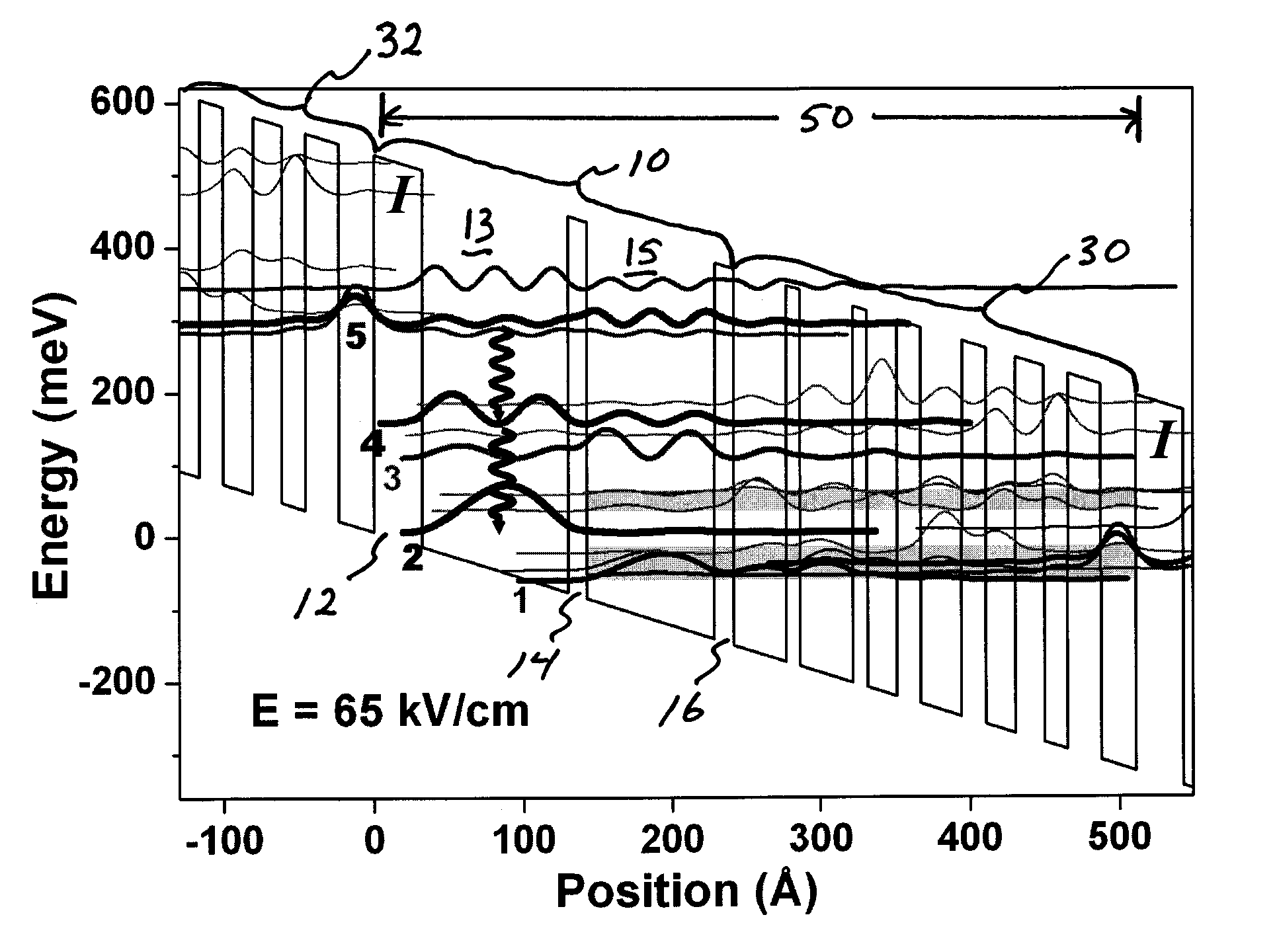
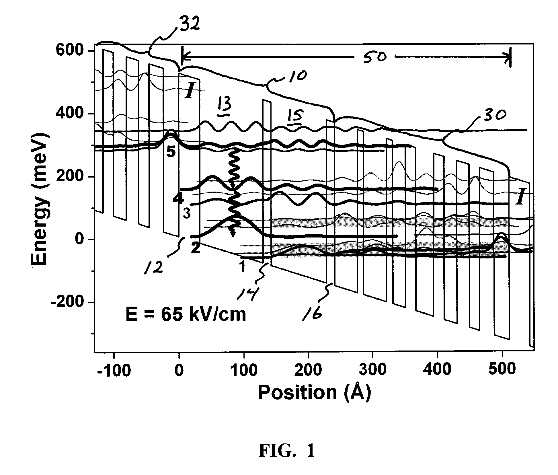
[0020]Turning first to FIG. 6, concepts common to the embodiments of the present invention described herein are shown illustrating certain advantages provided by QC photon sources, such as QC lasers, in accordance with the present invention. QC lasers of the present invention include at least two quantum wells and utilize at least one lasing transition between two excited states, e.g., the second- and first-excited states, of the constituent quantum well(s) of the active region. Such an excited state architecture comprising a lasing transition between two excited states has the potential for improving QC laser performance in at least two ways. First, the dipole matrix element between consecutive higher-level states is in general larger than between lower-level states, FIG. 6. Second, the wider active region wells that result from the excited state architecture of the present invention reduce the effects of scattering caused by interface roughness.

[0021]The gain coefficient g of a QC...


PUM


Abstract

A quantum cascade source, such as a QC laser, is provided comprising a plurality of repeat units each including an active region and an injector region. The active region includes at least two quantum wells that, in response to an applied electrical bias, provide a first, second, and third electron energy level, each resulting from a respective quantum well excited state. The first and second energy levels are configured so that an electron transition from the first energy level to the second energy level emits a photon of a selected wavelength. The second and third energy levels are configured so that an electron transition from the second energy level to the third energy level comprises a nonradiative transition to empty the second energy level sufficiently quickly to promote a population inversion between the first and second energy levels.

Description

GOVERNMENT LICENSE RIGHTS[0001]Pursuant to 35 U.S.C. §202(c) it is acknowledged that the United States Government may have certain rights in the invention described herein, which was made in part with funds from the Defense Advanced Research Projects Agency, Grant Number (L-PAS) DE-AC05-76RL01830.FIELD OF THE INVENTION[0002]The present invention relates generally to a quantum cascade (QC) photon source and more particularly, but not exclusively, to a quantum cascade laser that utilizes wide active region quantum wells to create a lasing transition between the excited states of the constituent wells.BACKGROUND OF THE INVENTION[0003]Quantum cascade (QC) lasers have made possible the development of mid-infrared technologies—such as room temperature and compact trace gas sensing systems—that, before the QC laser's invention in 1994, were not feasible due to the lack of a high performing mid-infrared laser. See, for instance, J. Faist et al., Science, 264, 553-556 (1994) and C. Gmachl et...

Claims


Application Information

Patent Timeline
Patent Type & Authority Applications(United States)
IPC IPC(8): H01S5/34H01L33/00
CPCB82Y20/00H01S5/024H01S5/3402H01S5/3415
Inventor GMACHL, CLAIRE F.FRANZ, KALE J.
Owner PRINCETON UNIV
Why Eureka
Try Eureka