Cosmetics case

a cosmetics and case technology, applied in the field of cosmetics cases, can solve the problems of increasing production costs, unnecessary waste, and noise generated by clicks

Active Publication Date: 2008-11-13
CHO KYU SUK
View PDF3 Cites 31 Cited by
  • Summary
  • Abstract
  • Description
  • Claims
  • Application Information

AI Technical Summary

Benefits of technology

[0014]The present invention provides a cosmetics case capable of rotating in both directions, in which rotation in one direction permits grinding of solid powder and rotation in the other direction permits pressing down of the surface of the solid powder, thereby preventing the ground powder from being discharged outwards while a user carries the cosmetics case.
[0015]The present invention further provides a cosmetics case, in which the solid powder is located adjacently below a rotatable member by tension of a spring installed in an intermediate case for supporting the bottom of a powder case, thereby easily grinding the solid powder.
[0016]The present invention further provides a cosmetics case, in which the spring is located at a fixed position by spring fixing protrusions of the intermediate case, and thus tension of the spring is uniformly applied to a central portion of the powder case, thereby easily grinding the solid powder.

Problems solved by technology

The conventional cosmetics case 100 includes the above-described seven components, and the lower body 103 is formed of a double structure, thereby increasing production costs because many processes are required to produce the cosmetics case 100.
Further, when a user uses the cosmetics case 100, noise is generated due to click caused at a specified interval when rotating the cosmetics case 100.
The user is reluctant to use the powder stained with impurities, and thus throws away the stained powder, thereby causing an unnecessary waste.

Method used


Image

  • Cosmetics case
  • Cosmetics case
  • Cosmetics case

Examples


Embodiment Construction

[0029]Exemplary embodiments of the present invention are described with reference to the accompanying drawings in detail. The same reference numbers are used throughout the drawings to refer to the same or like parts. Detailed description of well-known functions and structures incorporated herein may be omitted to avoid obscuring the subject matter of the present invention.

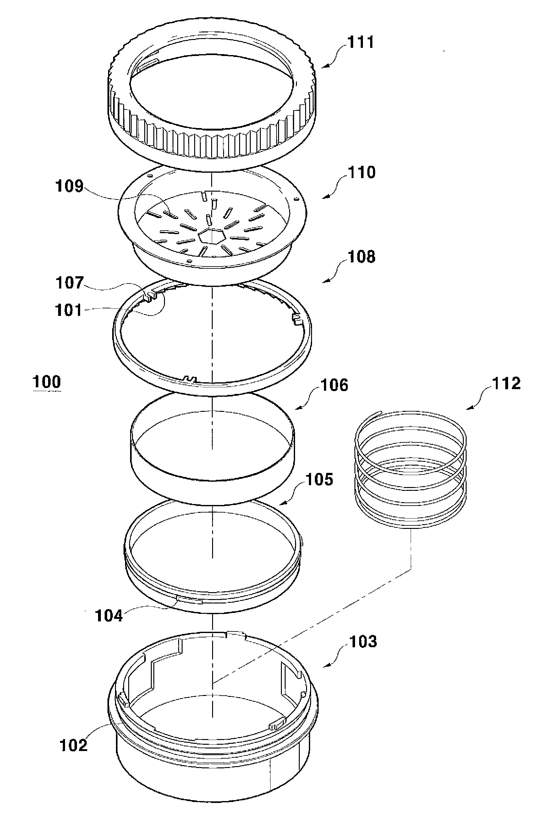
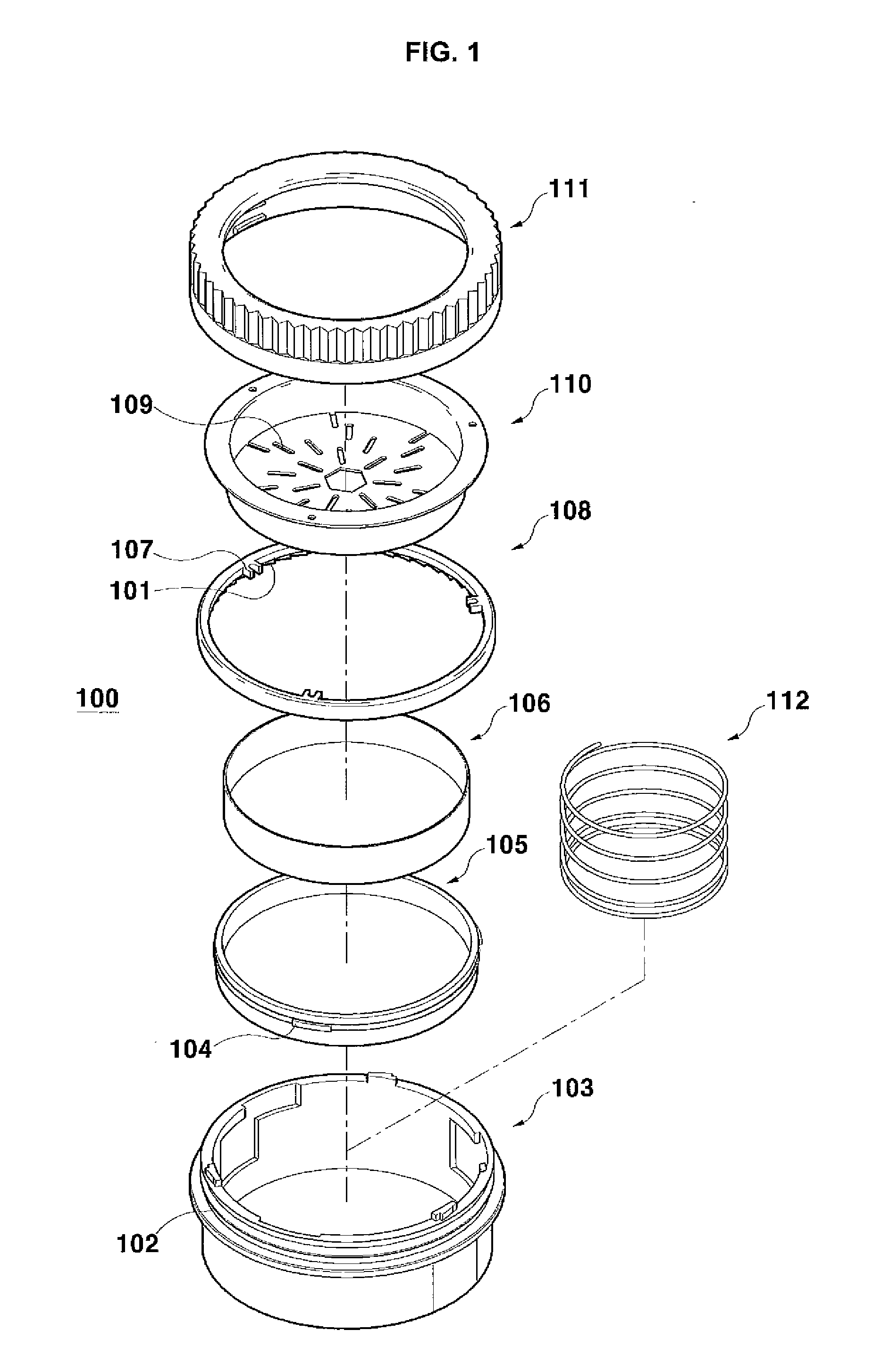
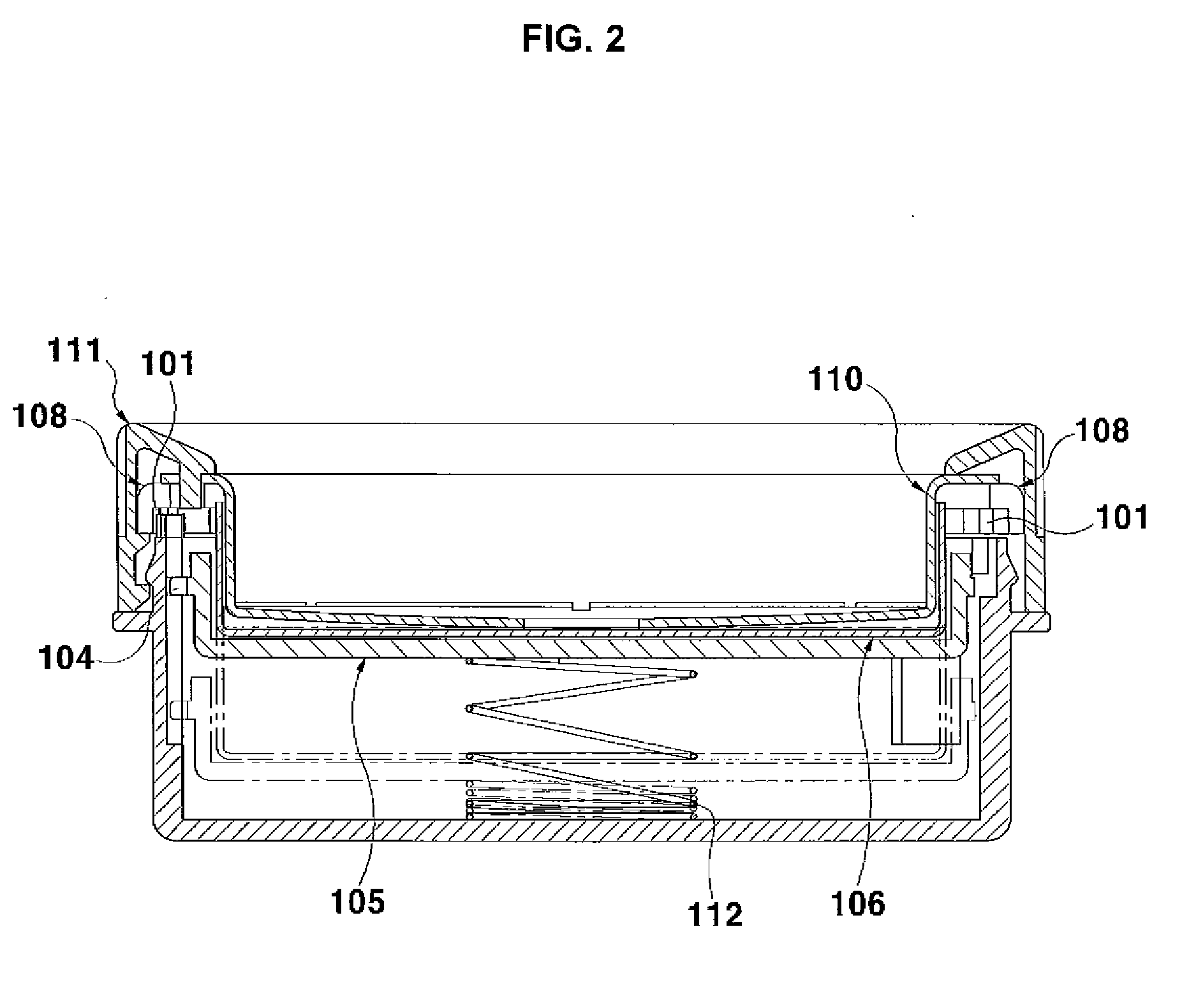
[0030]FIG. 3 is an exploded perspective view illustrating a configuration of a cosmetics case according to an exemplary embodiment of the present invention. FIG. 4 is a perspective view of a coupled state of the cosmetics case of FIG. 3, FIG. 5 is a cross-sectional view of a coupled configuration of FIG. 4, FIG. 6 is a perspective view illustrating the cosmetics case containing solid powder according to the present invention, FIG. 7 is a perspective view illustrating application of the cosmetics case according to the present invention, FIG. 8 is a bottom view of a configuration illustrating that a rotatable member...


PUM


Abstract

The present invention relates to a cosmetics case including a cover having a lock protrusion and a hinge protrusion; a base case to which the cover is pivotally connected; an intermediate case installed in the base case and in which a button and a spring are installed; a powder case receiving solid powder therein, installed in the intermediate case and supported by the spring; and a grinding member rotatably installed in a coupling groove of the intermediate case to grind the surface of the solid powder received in the powder case. The present invention provides the cosmetics case capable of rotating in both directions, in which rotation in one direction permits grinding of the solid powder and rotation in the other direction permits pressing down of the surface of the solid powder, thereby preventing the ground powder from being discharged outwards, and after use, the cover is closed to prevent impurities from being put into the solid powder.

Description

BACKGROUND OF THE INVENTION[0001]1. Field of the Invention[0002]The present invention relates to a cosmetics case for grinding solid powder, and in particular, to a cosmetics case with which a user grinds and uses a desired amount of solid powder, and, after using the powder, closes a cover to prevent the ground powder from being discharged outwards.[0003]2. Description of the Related Art[0004]Generally, cosmetics containers, for example a powder case, are variously developed according to their structures such as a type and opening and closing methods of a cover. Most women carrying facial powder in their handbags or bags take out and use the powder for beauty at a proper time.[0005]Therefore, most consumers demand cosmetics containers to be compact, and to be convenient to carry and use. To meet the demands, manufacturers try to produce cosmetics containers that are convenient to use.[0006]FIG. 1 is an exploded perspective view of a conventional cosmetics case for grinding solid po...

Claims


Application Information

Patent Timeline
Patent Type & Authority Applications(United States)
IPC IPC(8): A45D33/26A45D33/00
CPCA45D33/006A45D33/04A45D33/06A45D33/16A45D40/222A45D40/24
Inventor CHO, KYU SUK
Owner CHO KYU SUK
Why Eureka
Try Eureka