Adapter rail

Inactive Publication Date: 2008-11-13
CS DIGITAL_FABRIC
View PDF6 Cites 1 Cited by
  • Summary
  • Abstract
  • Description
  • Claims
  • Application Information

AI Technical Summary

Benefits of technology

[0011]It is therefore desirable to provide an adapter rail which can be fitted into the base frame of the profile rail system with the least possible complexity.
[0012]Furthermore, it is desirable to increase the flexibility of profile rail systems, and in particular to make it possible to combine the profile rail system with a tensible surface material, with at the same time simple fitting.
[0018]In one exemplary embodiment the push-in region and the section are formed on adjacent long sides of the adapter rail. This can have a particularly favourable effect for the fitting and fixing process of the adapter rail in the profile rail system if the contact region or the support surface is brought about by pivoting the section and provides good manageability during production of the adapter rail.
[0022]In one exemplary embodiment the adapter rail has a bar on one face side which can be inserted complementarily to an indentation formed in the opposite face side, and in particular can be fixed by means of snap-on or screw connections. In this way the stability of the adapter rails can advantageously be increased even further.
[0024]The profile rail system according to the invention has a base frame in which a fitting region for accommodating wall elements is formed, at least two adapter rails according to the invention being insertable into the base frame in order to fit or retrofit the base frame with a tensible surface material. Already existing systems can thus be provided with a flexible surface material by means of which the profile rail system is provided with mobility and flexibility due to the substantially simpler transportation of the flexible tensible surface material.

Problems solved by technology

With these systems the complexity of fitting is very high, among other things due to the plurality of accessories required.
The contact surfaces between two profile rails are generally small, and due to this a high level of loading with torsion or shearing forces cannot be compensated sufficiently.
In this way it is possible to reduce the number of fitting elements, especially as one can dispense with providing projections or bars, however there is the danger that the retention by means of bolts can be ripped out easily with statically higher loads.
This type of fitting is also very time-consuming and complex.
It is common to all of the previously described systems that they are designed such that they can only be equipped with a single, previously determined locking system.
This also proves to be very complex.
It is a disadvantage here that only the profiles especially designed for this can be fitted to the base frame, and only very specific types of inserts or partition walls with very specific, size-accurate types of profile rails can be fitted together.
The bolting of base frames and of profile rails and the adapter rails is complex and can also necessitate the complex opening of already pre-fitted base frames.

Method used


Image

  • Adapter rail
  • Adapter rail
  • Adapter rail

Examples


Embodiment Construction

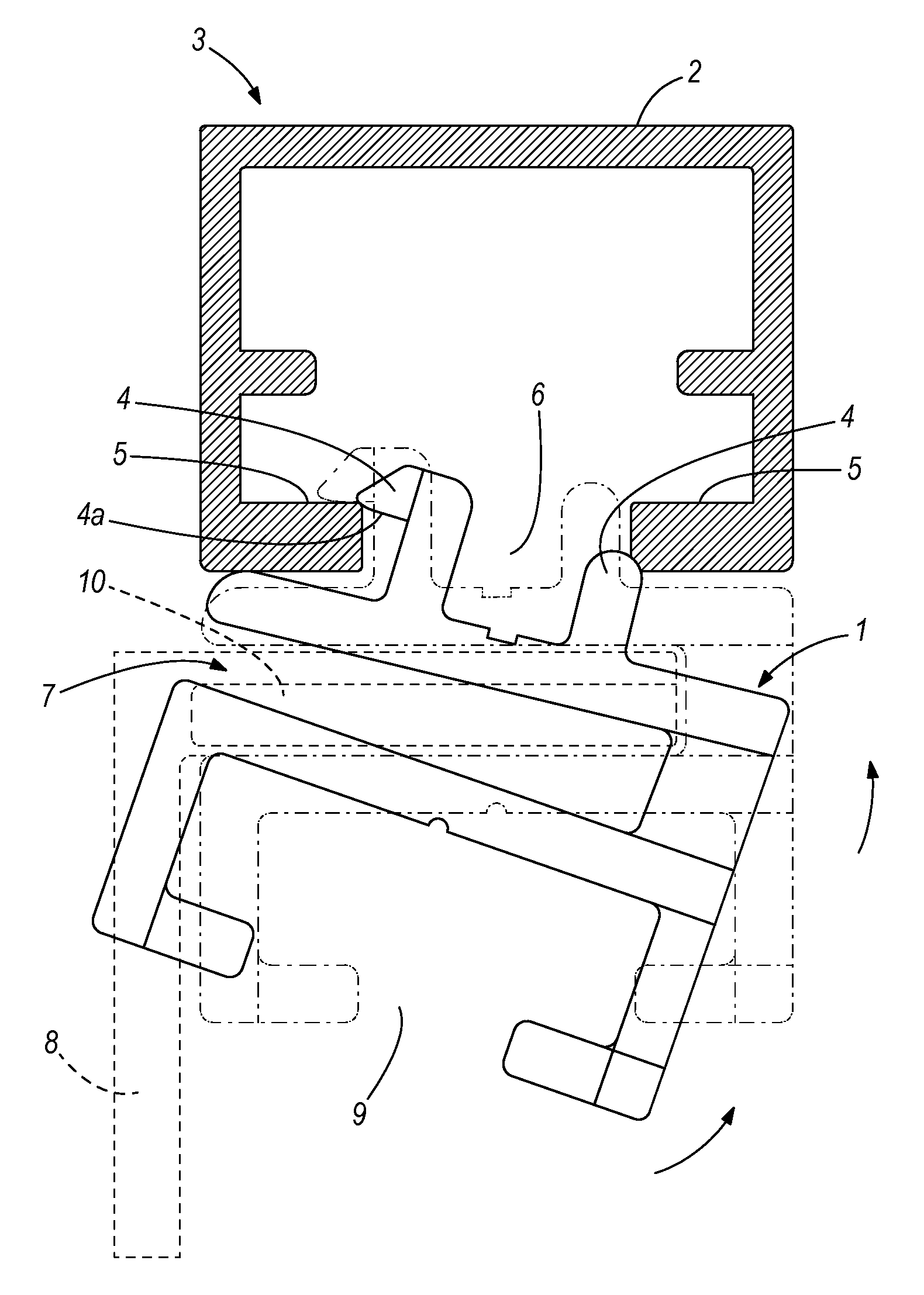
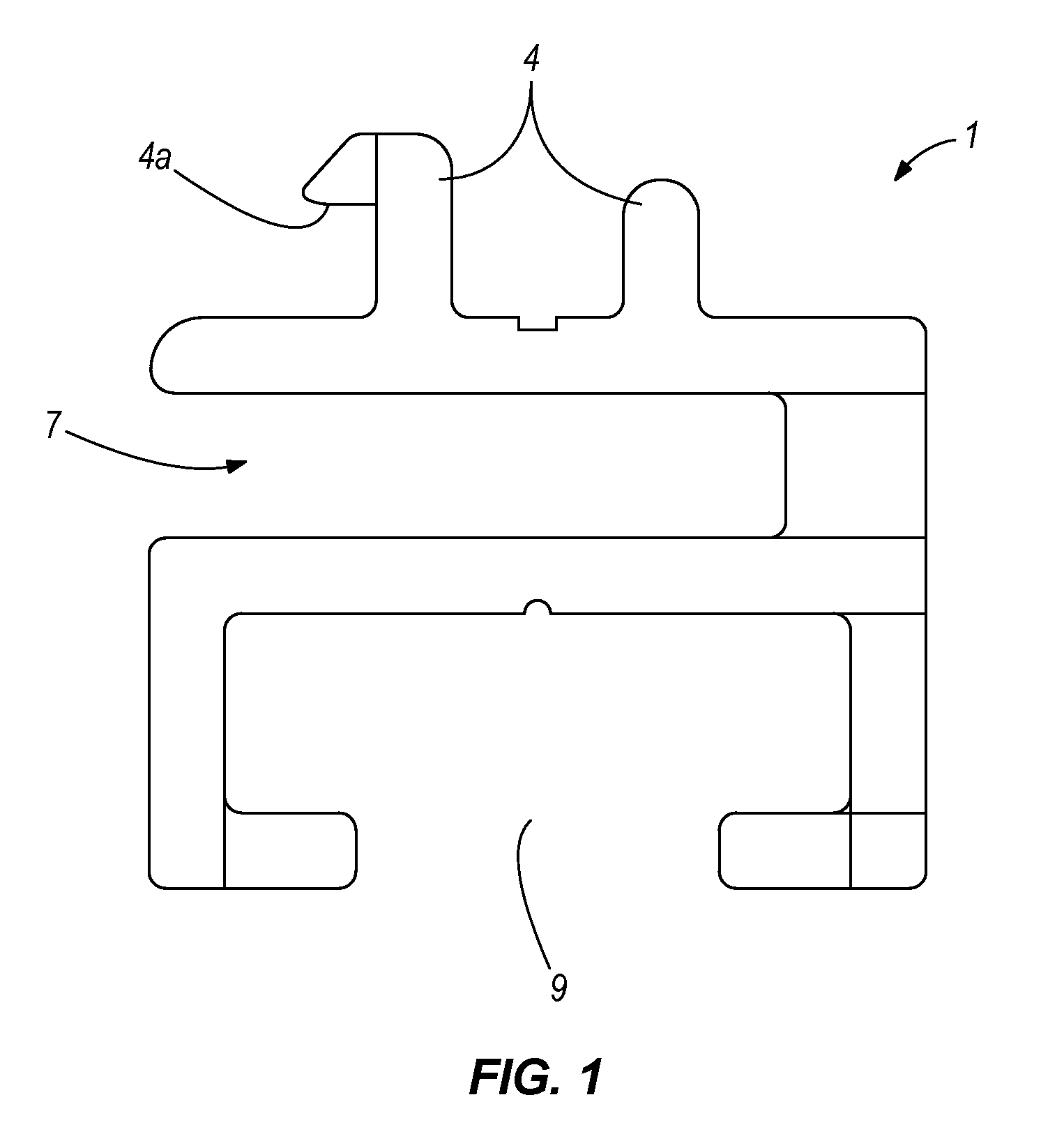
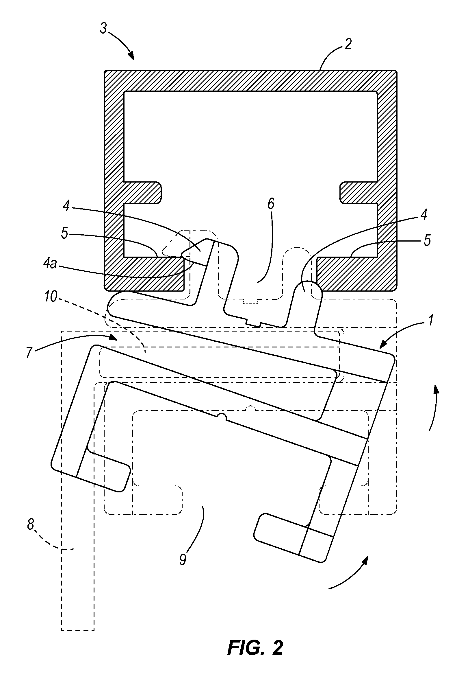
[0028]FIG. 1 shows an adapter rail 1 according to the invention to be disposed in a base frame 2 of a profile rail system 3. The adapter rail 1 has a two-part section 4 here in the form of two bar-shaped projections, one of the bars having on its free end a base element in the form of a substantially triangular projection by means of which the section can be fixed releaseably with force and form closure by pivoting it into an undercut 5 of a fitting region 6 of the base frame 2.

[0029]Beneath the section 4 the adapter rail 1 has a push-in region 7 for accommodating a tensible surface material B. A particularly simple type of fitting is produced if the surface material B is reinforced with so-called fitting strips 10 made of a flexible material such as for example silicone. Both the push-in region 7 and the section 4 extend respectively over the whole long side of the adapter rail 1.

[0030]In this exemplary embodiment the long aides are disposed adjacent to one another. It is conceivab...


PUM


Abstract

The invention relates to an adapter rail to be disposed in a base frame of a profile rail system which has a section with which it can be fixed releaseably by force and / or form closure within a fitting region of the base frame the adapter rail having a push-in region in order to accommodate a tensible surface material. The force and / or form closure is established by the insertion of the tensible surface material into the push-in region between the section and the fitting region.

Description

RELATED APPLICATIONS[0001]This application claims priority to U.S. Provisional Patent Application Ser. No. 60 / 906,203 filed on Mar. 12, 2007.FIELD OF THE INVENTION[0002]The present invention relates to a profile rail system and to an adapter rail to be disposed in a base frame of the profile rail system and which has a section with which it can be fixed releaseably by force and / or form closure within a fitting region of the base frame.BACKGROUND OF THE INVENTION[0003]These types of profile rail system are generally known. In particular in the field of exhibition stand construction building block-type framework systems are used with the aid of which exhibition stands corresponding to the ideas and needs of the exhibitors can be assembled. The profile rail systems generally have a base frame comprising vertically and horizontally extending bar profiles. The bar profiles are often made of aluminium and generally have a square or octagonal cross-section, and on each of their long sides ...

Claims


Application Information

Patent Timeline
IPC IPC(8): A47G5/00
CPCA47B96/145E04B2/7854E04B9/008F16B12/38
Inventor HANSEN, JURGENZOLLER, PETER
Owner CS DIGITAL_FABRIC
Why Eureka
Try Eureka