Power assisted bicycle with regenerative function

a technology of regenerative function and power assisted bicycle, which is applied in the direction of mechanical actuated clutches, interlocking clutches, transportation and packaging, etc., can solve the problems of long distance between the motor and the secondary battery, difficult mounting both the motor and the transmission on the rear axle, and difficulty in steering. to achieve the effect of improving the steering ability of the bicycle, saving assisting power, and increasing the distance the bicycle can travel

Inactive Publication Date: 2014-04-01
NTN CORP
View PDF16 Cites 15 Cited by
  • Summary
  • Abstract
  • Description
  • Claims
  • Application Information

AI Technical Summary

Benefits of technology

[0021]An object of the present invention is to provide a power-assisted bicycle of the center motor type including an internally mounted transmission and having a regenerative function with the least complexity of the structure.

Problems solved by technology

But such a hub-motor type bicycle has a problem in that the distance between the motor and the secondary battery is long and thus it is necessary to connect them thorough a long wire.
Further, if the motor is mounted on the front axle, steering becomes difficult.
Also, it is difficult to mount both the motor and the transmission on the rear axle.
The hub motor type has a problem in that besides a motor, a speed reducer has to be mounted in the rear hub too, so that it is difficult to use a speed reducer which is large enough to provide high speed reduction ratios, which in turn makes it impossible to produce large torque.
Also, since heavy objects are mounted at locations apart from the center of gravity of the bicycle, steerability of the bicycle is not good.
Further, since the distance between the motor and the battery is long, it is necessary to connect them thorough a long wire.
Still further, since shock from the wheel is directly transmitted to the speed reducer and the motor, they tend to malfunction.
An externally mounted transmission is simple in structure and lightweight, but its sprockets and chain tend to quickly become worn and its chain can easily separate.
But the conventional internally mounted transmissions cannot transmit reverse input from the wheel to the rear sprocket through the rear hub, and thus cannot turn the center motor for regeneration.
But the two separate power transmission means would markedly lower the value of the bicycle from the viewpoint of layout and cost.

Method used


Image

  • Power assisted bicycle with regenerative function
  • Power assisted bicycle with regenerative function
  • Power assisted bicycle with regenerative function

Examples


first embodiment

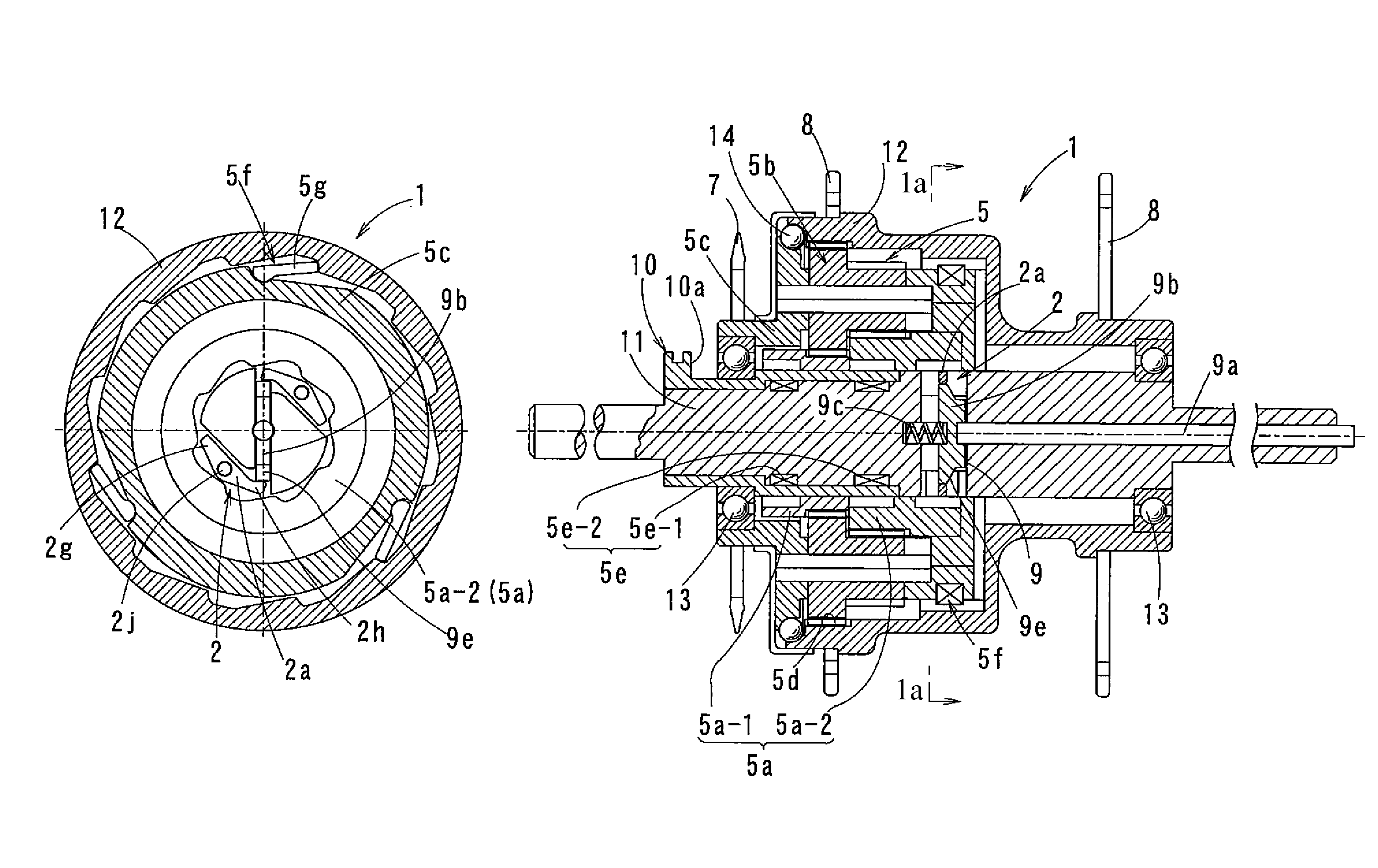
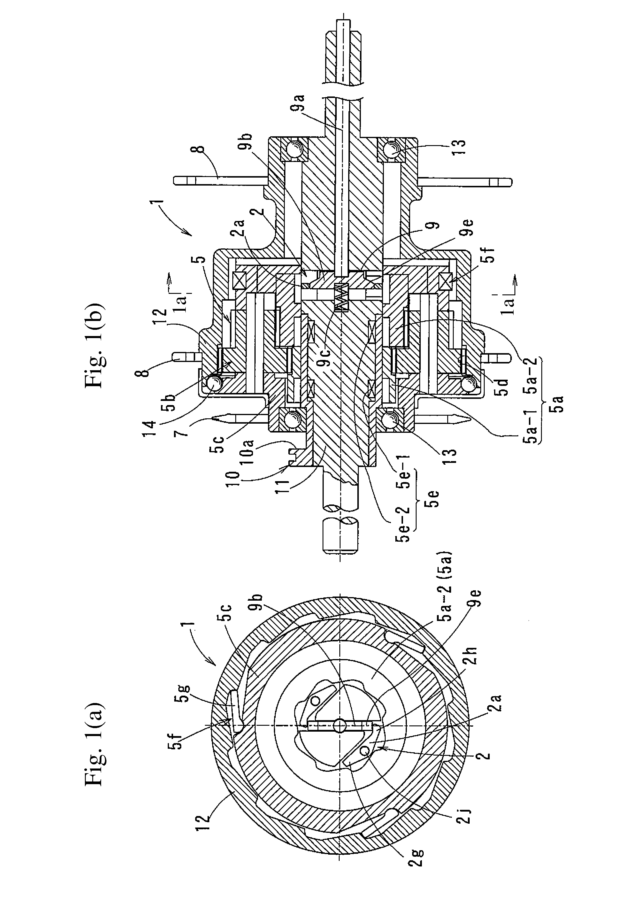
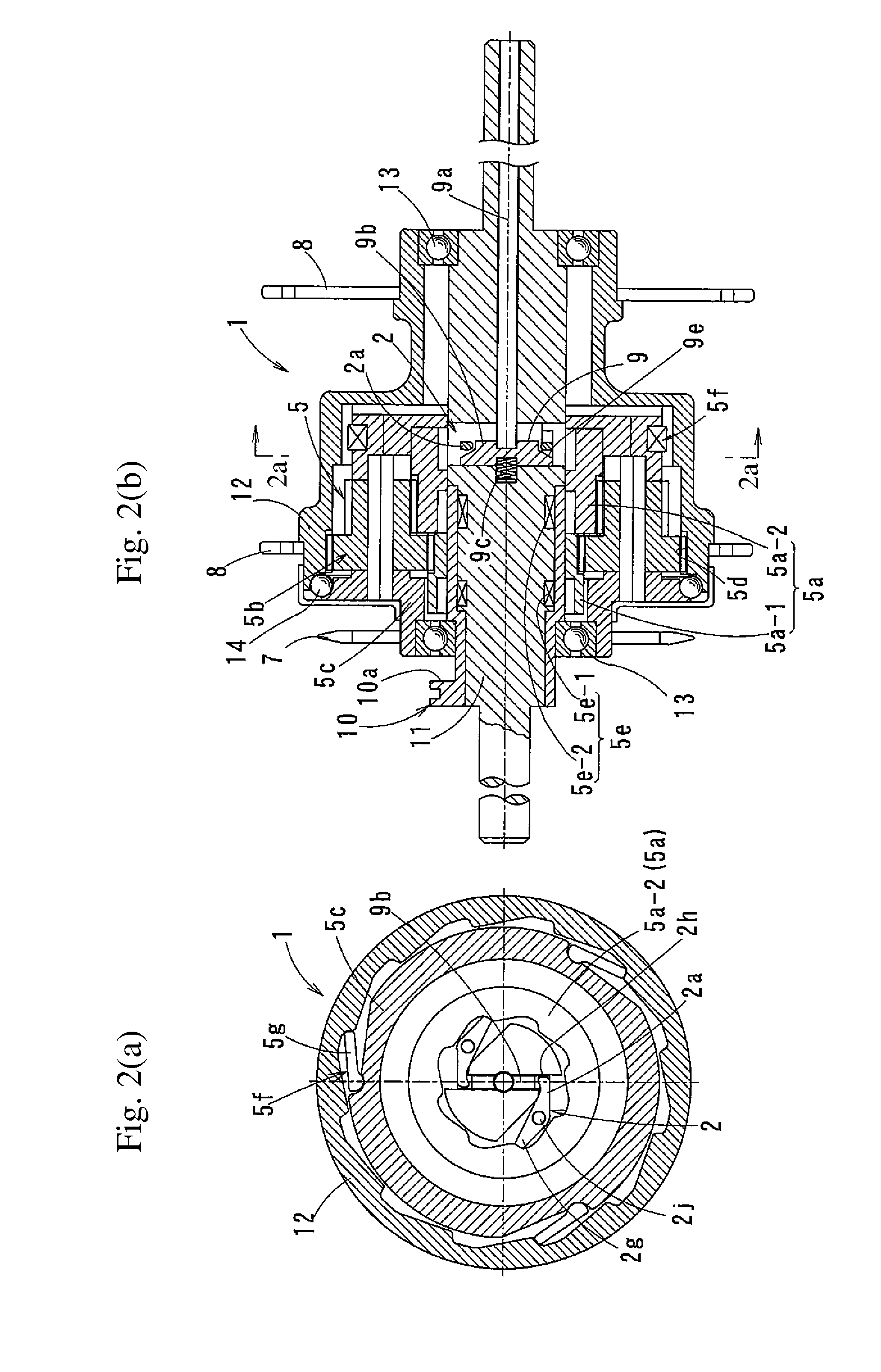
[0128]FIGS. 1 and 2 show the first embodiment of the present invention. The power-assisted bicycle of this embodiment is of the center-motor type in which a secondary battery and a drive-assisting motor (center motor unit C) are mounted on a frame connecting the front and rear wheels together at around the center between the front and rear wheels.

[0129]FIG. 27 is a side view of a typical power-assisted bicycle B that represents each of this and the following embodiments. With this bicycle, manual force applied to the pedals 70 is transmitted to the axle 11 of the rear wheel through a driving force transmission mechanism comprising a crankshaft 71, front sprocket 74, chain 73 and rear sprocket 7. The output of the motor is also added to the driving force transmission mechanism, thereby assisting in driving the bicycle.

[0130]Typically, as shown in FIG. 27, the center motor unit C is mounted near the crankshaft 71 with its battery 76 for driving the motor mounted in juxtaposition with ...

second embodiment

[0165]FIGS. 3 and 4 show the second embodiment of this invention. While the one-way clutch 2 for reverse input of this embodiment comprises a ratchet clutch as in the first embodiment, the clutch switching device 9 comprises a rotary member 9d extending along the axle 11. Otherwise, this embodiment is basically identical in structure to the first embodiment.

[0166]The rotary member 9d of this embodiment is a tubular member extending along the outer periphery of the axle 11 so as to be rotatable about the axle 11 relative to the axle 11. The rotary member 9d has circumferentially spaced apart slits 9f.

[0167]In the normal state, as shown in FIG. 3(a), the clutch pawls 2a of the one-way clutch 2 for reverse input are pivoted radially inwardly by the rotary member 9d.

[0168]When the rotary member 9d is rotated relative to the axle 11 until the slits 9f are radially aligned with the respective clutch pawls 2a, the clutch pawls 2a disengage.

[0169]When the clutch pawls 2a disengage, as sho...

third embodiment

[0176]FIGS. 5 and 6 show the third embodiment of the present invention. The one-way clutch 2 for reverse input of this embodiment comprises a roller clutch. Otherwise, this embodiment is basically of the same structure as the second embodiment.

[0177]As shown in FIG. 5, the one-way clutch 2 for reverse input of this embodiment comprises an outer ring 2d, an inner ring 2c, which is the axle 11, and rollers 2a′ configured to engage cam surfaces 2i formed on the axle 11 as the inner ring 2c.

[0178]The one-way clutch 2 further includes a retainer 2d for the rollers 2c which is directly coupled to the rotary member 9d of the clutch switching device 9.

[0179]The retainer 2d is coupled to the rotary member 9d such that in the normal state, each roller 2a′ is located in the widest area of a wedge-shaped space defined between the inner peripheral surface of the outer ring 2b and one of the cam surfaces 2i of the inner ring 2c (circumferential central portion of each of the cam surfaces 2i show...


PUM


Abstract

A center motor power-assisted bicycle includes an internal transmission and has a regenerative function. A transmission comprises, in a drive wheel hub, a planetary gear, a one-way clutch for reverse input, a clutch switching device, and, a sun gear and transmits driving force from a sprocket to the drive wheel. A transmission control mechanism selectively rotationally fixes the sun gear to the axle to change speed when driving force is applied. The clutch is disposed between the sun gear and the axle, and selectively rotationally fixes the sun gear to the axle by the operation of the clutch switching device when reverse input is applied. While the bicycle is driven, the clutch switching device moves the clutch to the rotatable state, to transmit driving force. While the bicycle is traveling without being driven, the clutch is locked, so that reverse input is transmitted to the sprocket.

Description

BACKGROUND OF THE INVENTION[0001]1. Technical Field[0002]This invention relates to a power-assisted bicycle including an electric motor that adds electrical driving force to the manual driving force.[0003]2. Background Art[0004]Such a power-assisted bicycle carries a battery that supplies electricity to the electric motor for producing the additional electrical driving force. Since it is desired that the bicycle can travel as long a period of time as possible between charges of the battery, a power-assisted bicycle is now known which is capable of using energy generated while the bicycle is traveling for regeneration of the battery.[0005]JP Patent Publication 8-140212A discloses a regeneration device for regenerating the battery including a control device for detecting the operation of the brake bars and controlling the regeneration device to regenerate the battery.[0006]In the case of a power-assisted bicycle including a motor and a transmission mounted around the axle (hub-motor t...

Claims


Application Information

Patent Timeline
Patent Type & Authority Patents(United States)
IPC IPC(8): F16D11/00
CPCF16D41/30B62M11/16B62M6/55
Inventor MAENO, EIJIITO, KIYOHIRO
Owner NTN CORP
Why Eureka
Try Eureka