Hammermill with rotatable housing

a rotatable, hammermill technology, applied in the field of hammermills, can solve the problems of heavy housing, wear of hammers and cutting plates, and difficulty in removing the working chamber and rotor assembly of such hammermills, and achieve the effect of convenient access and removal

Inactive Publication Date: 2008-11-13
CARTER DAY INDS
View PDF31 Cites 5 Cited by
  • Summary
  • Abstract
  • Description
  • Claims
  • Application Information

AI Technical Summary

Benefits of technology

[0005]Such a rotatable housing provides several advantages. For example, such a rotatable housing allows for easy access to the interior of the housing. After a housing body section is removed, the housing can be rotated

Problems solved by technology

Generally, the hammers and cutting plates wear during use.
The housing is typically heavy and is not easily removed.
Fur

Method used


Image

  • Hammermill with rotatable housing
  • Hammermill with rotatable housing
  • Hammermill with rotatable housing

Examples


Embodiment Construction

[0021]For the purpose of promoting an understanding of the principles of the invention, reference will now be made to the embodiments illustrated in the drawing and specific language will be used to describe the same. It will, nevertheless, be understood that no limitation of the scope of the invention is thereby intended; any alterations and further modifications of the described or illustrated embodiments, and any further applications of the principles of the invention as illustrated therein, are contemplated as would normally occur to one skilled in the art to which the invention relates.

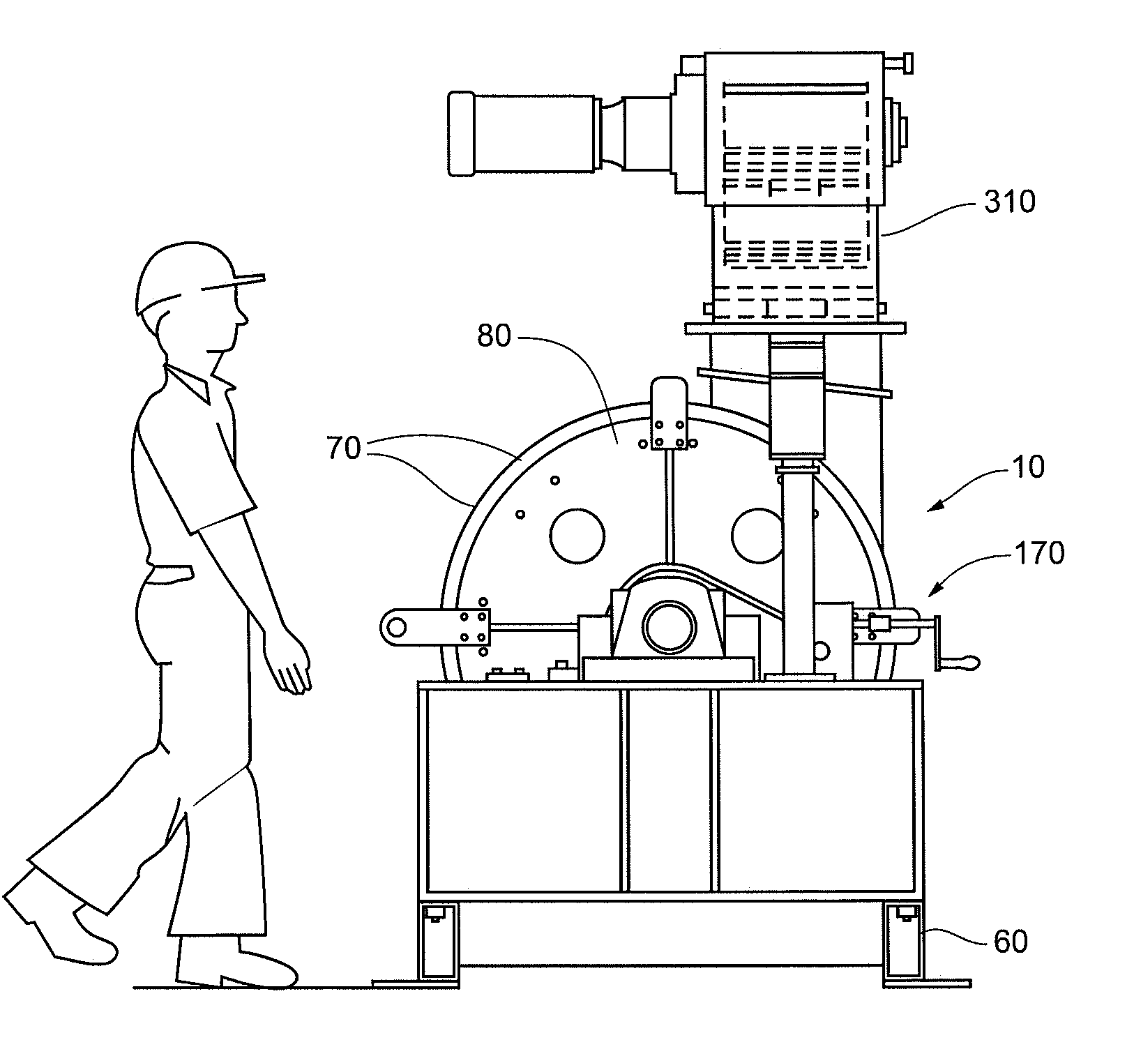
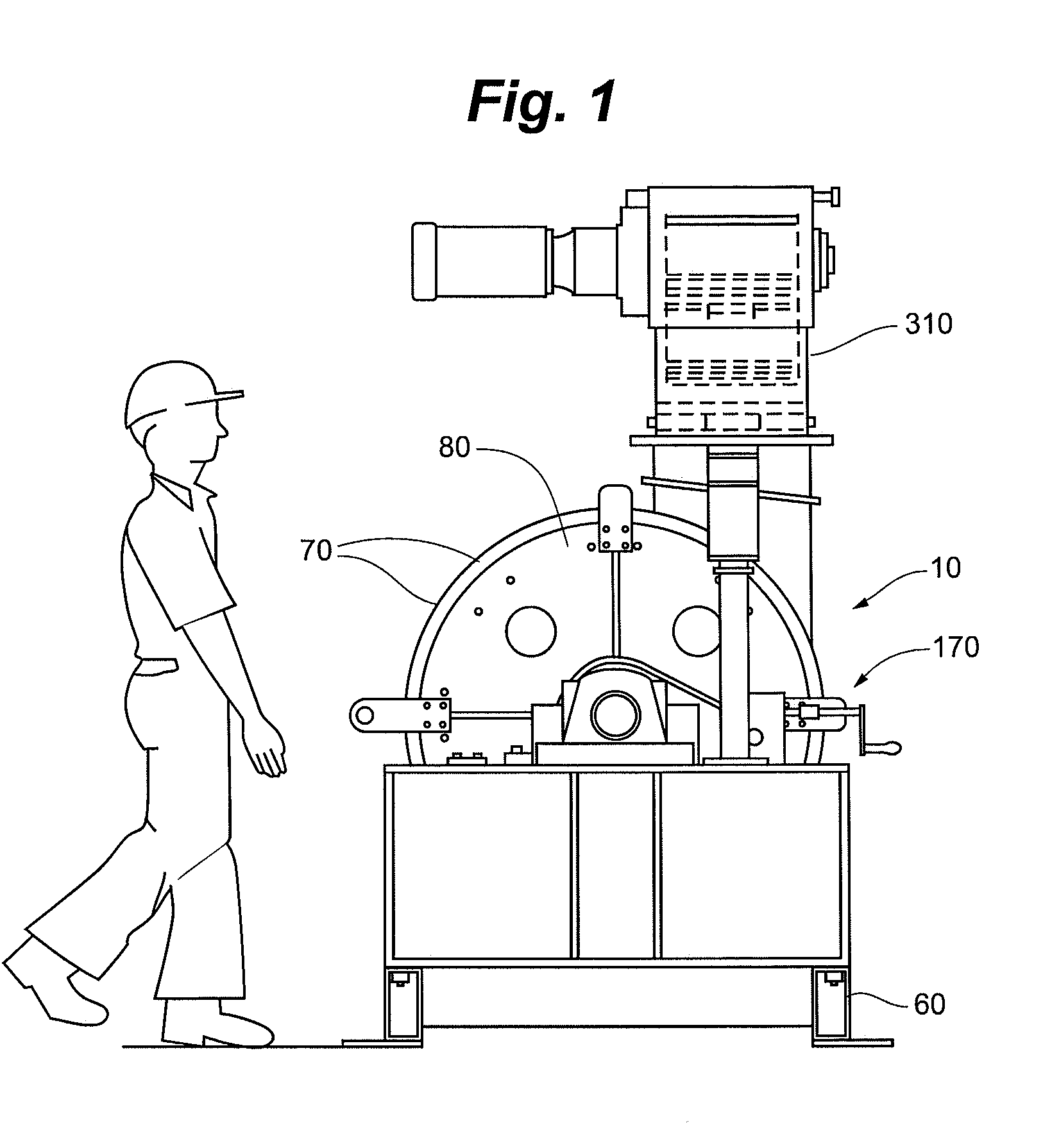
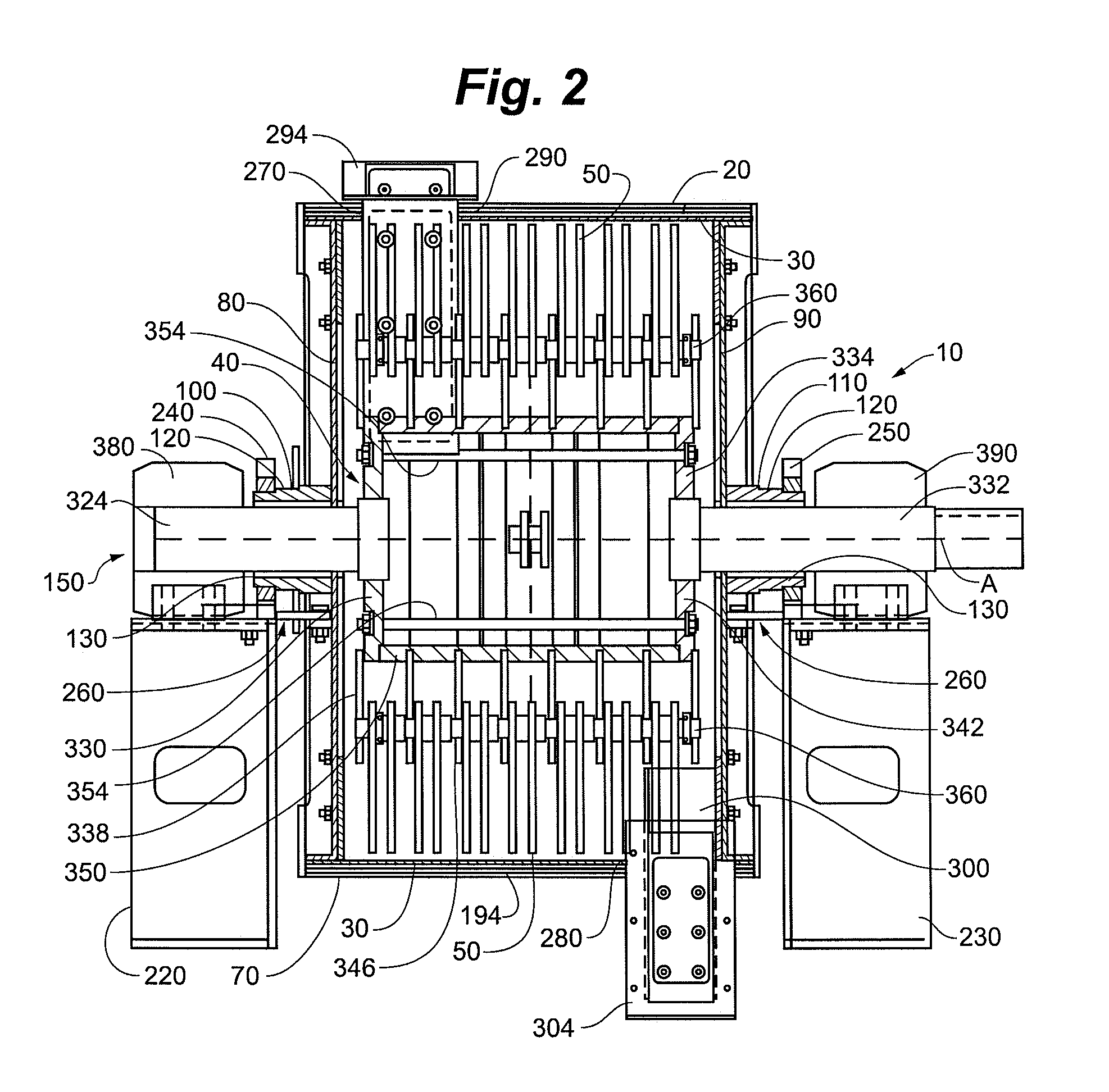
[0022]As shown in FIG. 1, embodiments of the invention include a hammermill 10 for comminuting material. The hammermill 10 includes a housing 20 and a cutting plate 30 and a rotor assembly 40 disposed therein, as shown in FIG. 2. A plurality of hammers 50 can be functionally coupled to the rotor assembly 40. The housing 20 can be rotatable about an axis of rotation. In some embodiments, the hamme...


PUM


Abstract

The invention includes a hammermill for comminuting material. The hammer includes a housing and a cutting plate disposed within the housing. A rotor assembly is rotatably mounted within the housing about an axis of rotation and a plurality of hammers are functionally coupled to the rotor assembly. The housing is rotatable about the axis of rotation.

Description

FIELD OF THE INVENTION[0001]The invention generally relates to hammermills.BACKGROUND OF THE INVENTION[0002]Hammermills are used for grinding or comminution of materials. Typically hammermills consist of a rotor assembly mounted on a driven rotor shaft inside a fixed housing that defines a working chamber. The fixed housing is fixedly connected to a base that also supports a motor for driving the rotor shaft. As the driven rotor shaft rotates it causes rows of hammers to impact and reduce the material within the working chamber. Cutting plates are mounted within the working chamber to promote reduction of the material.[0003]Generally, the hammers and cutting plates wear during use. In a typical hammermill, the fixed housing must be removed to gain access to the hammers and cutting plates. The housing is typically heavy and is not easily removed. Further, the working chambers and rotor assemblies of such hammermills are not easily removable from the hammermill base.SUMMARY OF THE INV...

Claims


Application Information

Patent Timeline
IPC IPC(8): B02C13/04
CPCB02C13/282B02C13/286B02C2013/2869
Inventor BEDNARSKI, JOSEPH JOHNHAUCH, DAVID A.
Owner CARTER DAY INDS
Why Eureka
Try Eureka