User-Defined Enablement Protocol

a user-defined and enablement protocol technology, applied in the direction of unauthorized memory use protection, digital storage, instruments, etc., can solve the problems of limiting the range and complexity of possible enablement protocols, making it more difficult for another person to learn the code by observation, and again simple for an unauthorised person to enter, etc., to achieve the effect of small display

Inactive Publication Date: 2008-11-13
ZETTA RES & DEV LLC RPO SERIES
View PDF8 Cites 213 Cited by
  • Summary
  • Abstract
  • Description
  • Claims
  • Application Information

AI Technical Summary

Benefits of technology

[0018]Prior art devices typically require touches or near touches within one or more pre-existing or specified areas to enable a particular pre-defined function. For instance, a simple keypad on a touch display provides alphanumeric material at specific predefined locations, and touches or near touches at these locations must be accomplished in a specific sequence to enable the function, e.g. to activate a device containing the touch display. However, the user-defined interface method according to the present disclosure has no such spatial or temporal indication to a user of where touches or near touches should be received to enable the function, thereby allowing a user to have complete freedom in regard to defining how the functionality of an electronic device associated with the interface is enabled by touch.
[0020]In one embodiment the present disclosure envisages no such spatial or temporal indication to a user. Rather a user can define a security code or ‘enablement protocol’ on the device or indeed on an apparatus separate from but operatively associated with the device by defining one or more touches to enable the aforementioned function. One such ‘touch’ may be for instance the touch of a thumb in the upper right hand corner of the screen or other touch sensitive area, or both. Alternatively, several touches at user-defined locations on the screen may enable the device. In another embodiment, a sequence of touches either at the user-defined locations or indeed anywhere on the screen can enable the functionality required. The timing or protocol (temporal sequence) of these touches must then be recreated to enable said function. In more complex arrangements both the spatial and temporal nature of the touches are examined to ensure that they meet the user-defined enablement protocol. In further arrangements, different types of touching bodies could enable different functions by performing otherwise identical enablement protocols. For example a swipe down one side of a touch screen with a stylus enables function A, while the same swipe with a finger enables function B. This embodiment expands the range of functions that can be performed with a limited range of gestures, or alternatively provides an additional security feature.
[0025]The disclosure as described is particularly useful for users with some form of physical handicap that may prevent them from using conventional touch screen devices. By providing complete freedom to an individual user to define enablement protocols for the various functions of a device, they may define the touches in terms of spatial and temporal parameters that they can easily replicate.
[0039]In one embodiment the touch-sensitive area is larger than the area of the display device and contains the display device within its borders. Generally, conventional touch-sensitive input devices include a display device that is at least as large as the touch-sensitive area. In one embodiment the touch-sensitive area is larger than the display itself and includes the display device within its borders. This is highly unusual but provides advantages over conventional systems, for example the opportunity of producing a smaller display with consequent power reduction. Also, by including the touch-sensitive area outside the display, the display itself is not obscured while input is applied via the touch-sensitive area. The touch portions / locations may be located on a first face of the touch-sensitive area, generally the display side, and / or a second opposite face of the touch-sensitive area. In one particular embodiment the touch portions / locations for enablement of the functions are arranged on the first and second opposite faces of the touch-sensitive area in such a way that they can be simultaneously operated by the thumb and fingers of a user.

Problems solved by technology

A known drawback here is that if an unauthorised person learns the alphanumeric code, it is simple for them to activate the mobile phone or log in to the computer system.
If the device is equipped with a touch screen so that the alphanumeric keys can be shown on a display, an additional level of security is available in that the locations of the keys can be scrambled either before or during entry of the code, making it more difficult for another person to learn the code by observation.
However once the code is known, it is once again simple for an unauthorised person to enter it.
Once again, there is no security once the unlock code (i.e. the path) is known, and the restriction to using direction keys limits the range and complexity of possible enablement protocols.
However in all these cases the user is either guided by displayed material or the gesture is predetermined, so there is limited opportunity for altering the functionality provided by the device or the mechanisms by which those functions are enabled.

Method used


Image

  • User-Defined Enablement Protocol
  • User-Defined Enablement Protocol
  • User-Defined Enablement Protocol

Examples


Embodiment Construction

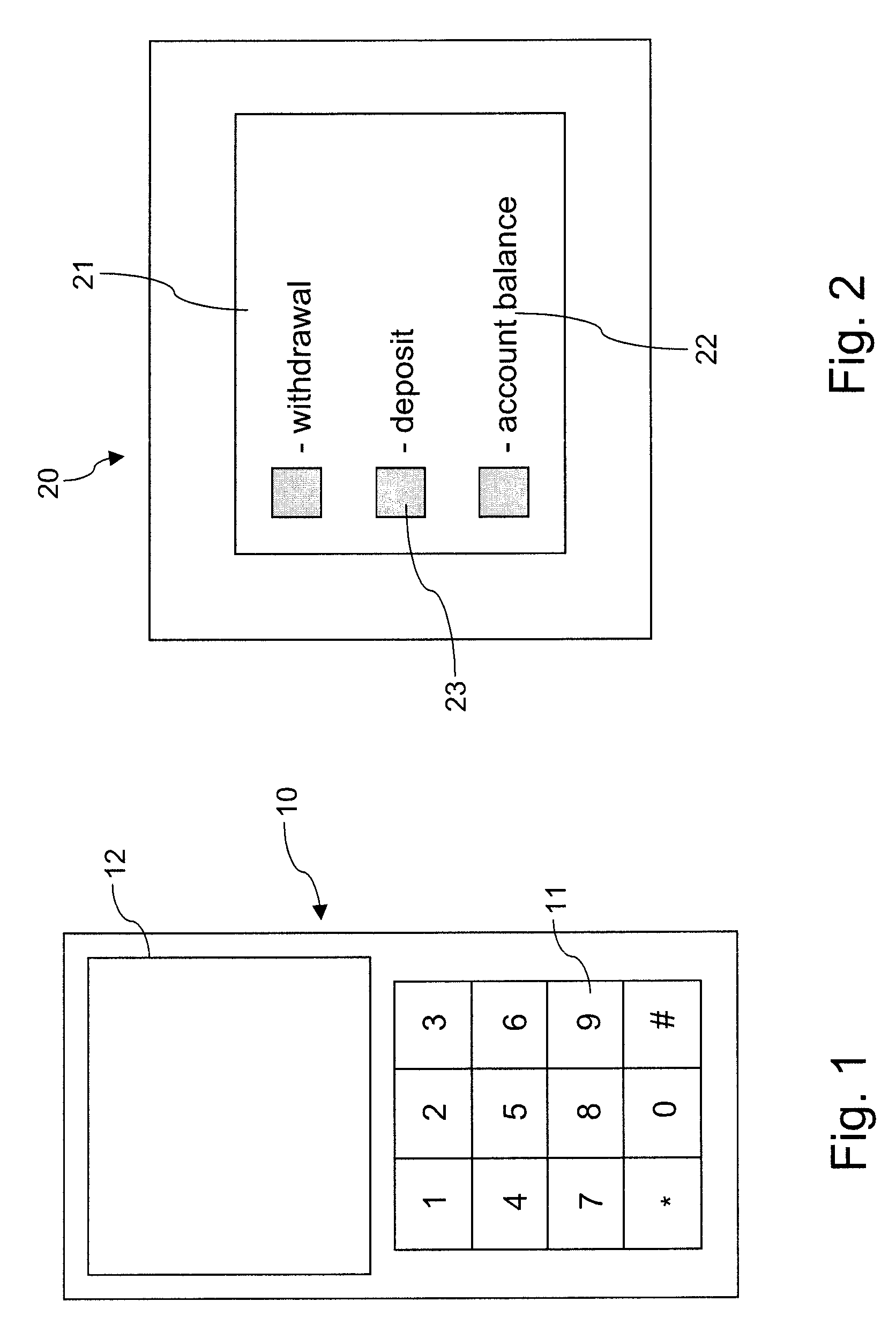
[0047]FIGS. 1 and 2 provide illustrations of prior art functionality in conventional devices.

[0048]FIG. 1 shows a mobile phone 10 with an alphanumeric keypad 11 and a display 12. In many instances the mobile phone can only be enabled when a user-defined security code is entered via the alphanumeric keypad 11. Alternatively the alphanumeric keypad may be provided on a touch-sensitive display (i.e. a touch screen) but once again the conventional device comprises a pre-defined arrangement of the enablement protocol such that if an unauthorised user were aware of the code e.g. 123, they could enable the device simply by engaging the predefined locations for numerals 1, 2 and 3.

[0049]FIG. 2 is an illustration of an automatic teller machine 20 with a touch sensitive display 21. This technology is similar to the mobile phone in FIG. 1, and in this instance various functions and spatial locations for enabling those functions are clearly defined on the display. The display includes indicia 2...


PUM


Abstract

A user interface method is disclosed. For a particular interface, such as a touch input device, the method involves defining an enablement protocol for a function and recording and retaining the enablement protocol of said function, such that a user enables the function by substantially reproducing the enablement protocol in the absence of spatial or temporal indication of at least a portion of the enablement protocol.

Description

CROSS-REFERENCE TO RELATED APPLICATIONS[0001]This application claims priority under the Paris Convention to Australian Provisional Patent Application No. 2007902519 filed on May 11, 2007, and Australian Provisional Patent Application No. 2007902517 filed on May 11, 2007, the contents of both of which are incorporated herein by reference.FIELD OF THE DISCLOSURE[0002]The present disclosure relates to user-defined enablement protocols for electronic devices. The disclosure has been developed primarily for providing an enhanced security means for enabling or executing functions of electronic devices through an interface such as a touch-sensitive display, and will be described hereinafter with reference to this application. However it will be appreciated that the disclosure is not limited to this particular field of use.BACKGROUND OF THE DISCLOSURE[0003]Any discussion of the prior art throughout the specification should in no way be considered as an admission that such prior art is widel...

Claims


Application Information

Patent Timeline
Patent Type & Authority Applications(United States)
IPC IPC(8): G06F3/041G06F21/22
CPCG06F3/04883G06F3/0416G06F3/0488
Inventor ATKINS, GRAHAM ROYMAXWELL, IAN ANDREW
Owner ZETTA RES & DEV LLC RPO SERIES
Why Eureka
Try Eureka