Moving Object Detection Apparatus And Method By Using Optical Flow Analysis

a technology of moving object and optical analysis, applied in the field of moving object detection apparatus and method by using optical analysis, can solve the problems of inapplicability of conventional moving object detection techniques to the detection of security events, inability to provide dynamic security support for conventional systems, and change of entire images, etc., and achieve the effect of stably and difficult interference of noise errors

Active Publication Date: 2008-11-13
IND TECH RES INST
View PDF12 Cites 71 Cited by
  • Summary
  • Abstract
  • Description
  • Claims
  • Application Information

AI Technical Summary

Benefits of technology

[0014]The disclosed embodiment may detect all the moving objects in the foreground, and may detect the foreground moving object area correctly and stably. This invention may be applied on a movable or a fixed platform with only a single camera, and noise error is difficult to interfere with this invention.

Problems solved by technology

When security event occurs, the conventional system may not provide dynamic security support; therefore, the use of mobile camera is gaining popularity.
Nevertheless, the mobile camera may cause the entire image change, which may render the conventional moving object detection techniques inapplicable to the detection of security events.
In addition, the error may occur when the background object in the scene is too close to the camera.
However, the disadvantages may include the slow computation, requiring many cameras to obtain the depth information, and depth information difficult to obtain at smooth images.

Method used


Image

  • Moving Object Detection Apparatus And Method By Using Optical Flow Analysis
  • Moving Object Detection Apparatus And Method By Using Optical Flow Analysis
  • Moving Object Detection Apparatus And Method By Using Optical Flow Analysis

Examples


Embodiment Construction

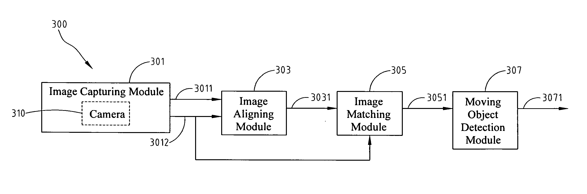
[0028]FIG. 3 shows a schematic view of an exemplary moving object detection apparatus by using optical flow analysis, consistent with certain disclosed embodiments. Referring to the exemplary apparatus, a moving object detection apparatus 300 by using optical flow analysis may include an image capturing module 301, an image aligning module 303, an image matching module 305, and a moving object detection module 307.

[0029]Image capturing module 301 successively captures a plurality of images; for example, in a scene under surveillance, a camera 310 moves or remains still to capture a plurality of images. Image capturing module 301 is applied as an input element to moving object detection apparatus 300. Based on a previous image 3011 and a neighboring posterior image 3012, image aligning module 303 obtains an aligned previous image 3031. After the image is aligned, image matching module 305 takes pixel as a unit, and applies optical flow tracing to find the optical flow trajectory of e...


PUM


Abstract

Disclosed is a moving object detection apparatus and method by using optical flow analysis. The apparatus includes four modules of image capturing, image aligning, pixel matching, and moving object detection. Plural images are successively inputted under a camera. Based on neighboring images, frame relationship on the neighboring images is estimated. With the frame relationship, a set of warping parameter is further estimated. Based on the wrapping parameter, the background areas of the neighboring images are aligned to obtain an aligned previous image. After the alignment, a corresponding motion vector for each pixel on the neighboring images is traced. The location in the scene of the moving object can be correctly determined by analyzing all the information generated from the optical flow.

Description

FIELD OF THE INVENTION[0001]The present invention generally relates to a moving object detection apparatus and method by using optical analysis.BACKGROUND OF THE INVENTION[0002]Moving object detection plays an important role in the automatic surveillance systems. The image surveillance system analyzes the trajectory and behavior of moving objects in the surveillance images to detect the abnormal security events and notifies the security for handling the events.[0003]However, the conventional surveillance system usually sets up a plurality of fixed surveillance cameras in the environment under surveillance. When security event occurs, the conventional system may not provide dynamic security support; therefore, the use of mobile camera is gaining popularity. Nevertheless, the mobile camera may cause the entire image change, which may render the conventional moving object detection techniques inapplicable to the detection of security events.[0004]U.S. Pat. No. 6,867,799 disclosed a met...

Claims


Application Information

Patent Timeline
Patent Type & Authority Applications(United States)
IPC IPC(8): H04N7/18
CPCG06T7/2006G06T2207/10016G06T2207/30232G06T7/215
Inventor SHIH, MING-YUFU, BWO-CHAU
Owner IND TECH RES INST
Why Eureka
Try Eureka