
Moving Image Converting Apparatus, Moving Image Converting Method, and Computer Program

a technology of moving image and converting method, which is applied in the direction of color television with bandwidth reduction, television system, instruments, etc., can solve the problems of inability to obtain good visual information and hard for the viewer to follow all such different motions at the same time, and achieve the effect of suppressing image quality degradation and small imago quality degradation

Inactive Publication Date: 2008-11-13
SONY CORP
View PDF7 Cites 11 Cited by
  • Summary
  • Abstract
  • Description
  • Claims
  • Application Information

AI Technical Summary

Benefits of technology

[0057]According to an embodiments of the present invention, it determines an optimal compression processing mode corresponding to the motion of an object within an image and to the motion of the viewer's line of sight, and perform data conversion processing in the optimal mode for each of areas according to the determined mode. Therefore, data reduction processing is enabled independently of the motion of the viewer's line of sight and with extremely small imago quality degradation.
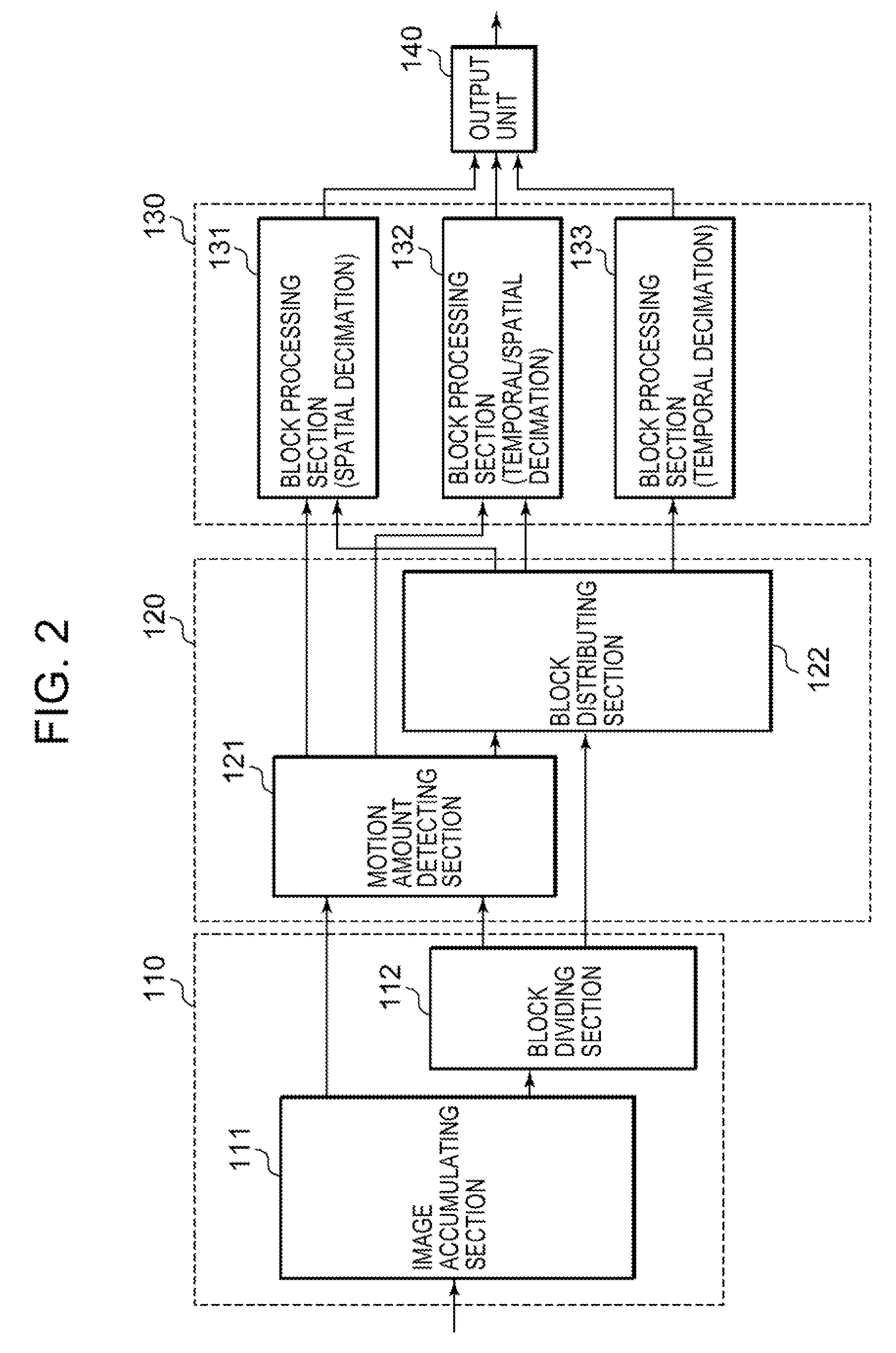
[0058]According to an embodiments of the present invention, it is configured to detect an object motion amount (block motion amount [Vs]) and a line-of-sight motion amount [Ve] in each of blocks forming moving image data, determine a sampling point phase change amount [Vp] on the basis of the detected object motion amount and line-of-sight motion amount, and execute spatial decimation processing by applying the determined sampling point phase change amount [Vp]. Therefore, when the viewer views the object by following its motion, the super-resolution effect can be induced, and even when the viewer does not view the object by following its motion, change in the arrangement of pixels forming the image can be minimized, whereby data conversion is realised in which image quality degradation is suppressed.
[0059]Furthermore, according to an embodiment of the present invention, it is configured, in spatial decimation processing with a decimation amount M, to select a plurality of optimal sampling point phase change amount candidates for obtaining image quality ratings which are equal to or greater than a preset reference rating with respect to the motion velocity of a block for processing under a motion-following viewing condition, using mapping data between the object motion velocity (or motion amount) and the image quality rating, which is generated on the basis of decimated data obtained by decimation processing with sampling point phase change amounts ranging from 0 to M−1, and to further select an optimal sampling point phase change amount for a non-motion-following viewing condition, from among the candidates. Therefore, data conversion is realized which enables presentation of high-quality images corresponding to various motion amounts of a block for processing and various line-of-sight motions of a viewer.

Problems solved by technology

It is hard for the viewer to follow all such different motions simultaneously.
Therefore, there is an issue such that the viewer, following the motion of a certain object, can obtain good visual information about that object, but for the other objects, he cannot obtain good visual information.

Method used


Image

  • Moving Image Converting Apparatus, Moving Image Converting Method, and Computer Program
  • Moving Image Converting Apparatus, Moving Image Converting Method, and Computer Program
  • Moving Image Converting Apparatus, Moving Image Converting Method, and Computer Program

Examples


Embodiment Construction

[0122]Configurations of a moving image converting apparatus, a moving image converting method, and / or a computer program, according to embodiments of the present invention will be described below with reference to the drawings. The description is given according to the following items:

[0123](1) Basic configuration, of moving imago converting apparatus utilizing super-resolution effect; and

[0124](2) Configuration of moving image converting apparatus for executing improved decimation processing.

(1) Basic Configuration of Moving Image Converting Apparatus Utilizing Super-Resolution Effect

[0125]First, a description will be given of the basic configuration of a moving image converting apparatus utilizing a super-resolution effect, which serves as the base of the present invention. This basic eon figuration is disclosed in detail in Japanese Patent Application Publication No. 2006-5904 filed earlier by the present applicant. This is a configuration that has realized data compression by di...


PUM


Abstract

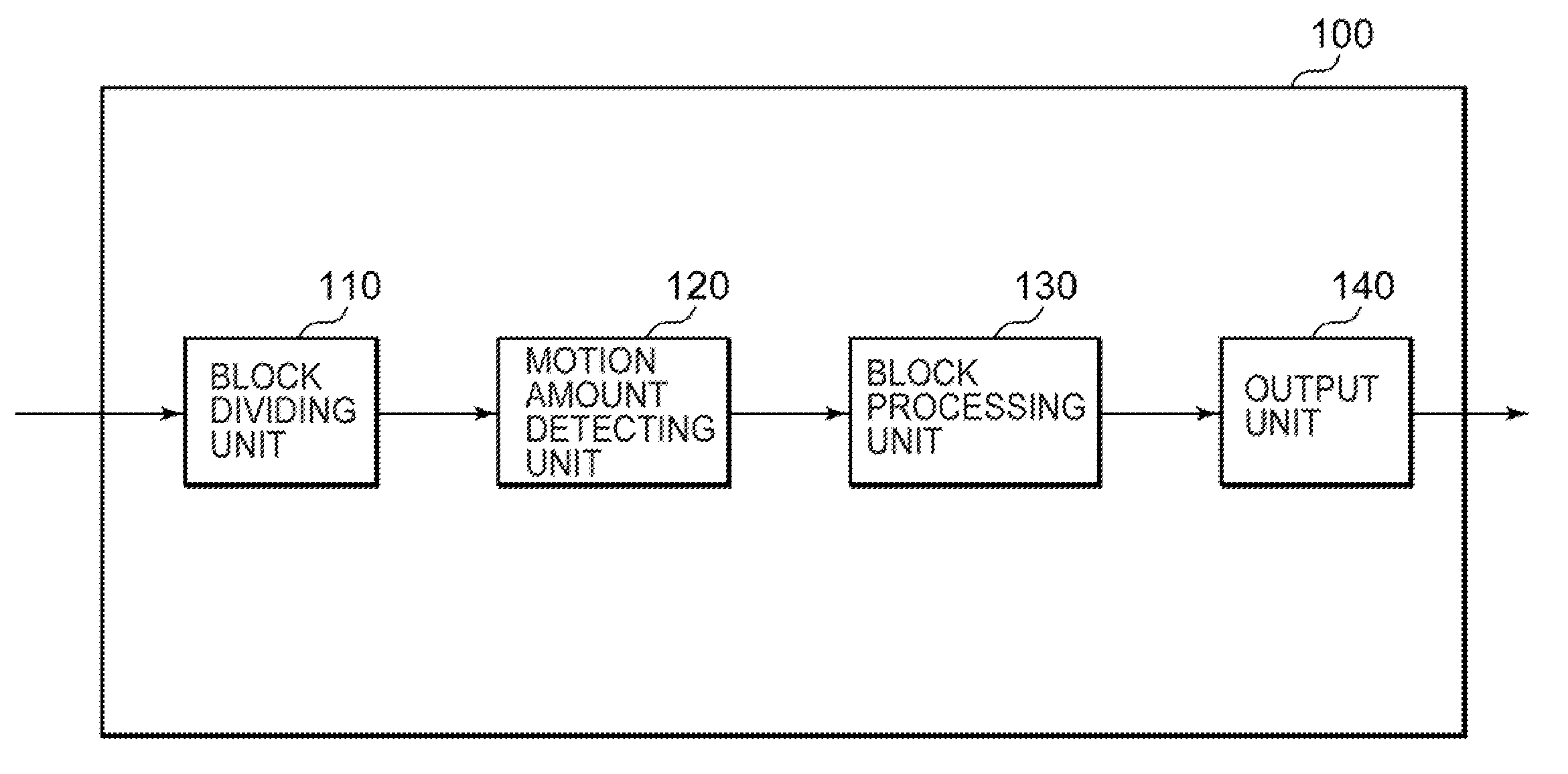
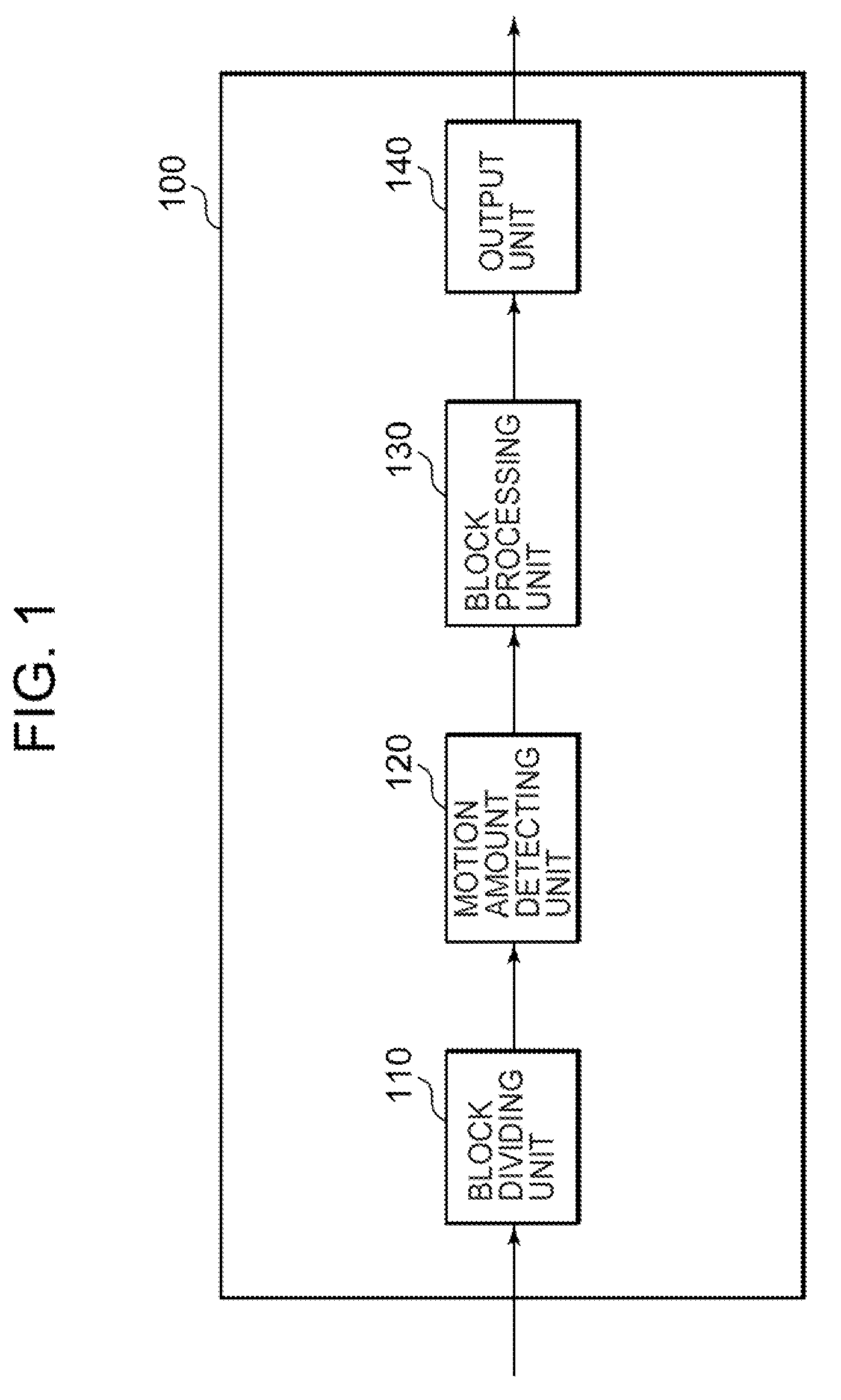
A moving image converting apparatus includes: a block dividing unit executing block division processing for each of frames that form the moving image data; a motion amount detecting unit detecting a block motion amount corresponding to a motion amount of an object contained in each of blocks obtained; a line-of-sight motion amount detecting unit calculating a line-of-sight motion amount of a viewer who views the moving image data; a sampling point phase change amount determining unit receiving the block motion amount and the line-of-sight motion amount as input, and determining a block-corresponding sampling point phase change amount to be applied to spatial decimation processing on each of the blocks; and a decimation executing unit receiving the blocks obtained as input, executing the spatial decimation processing on the inputted blocks, the spatial decimation processing being executed by applying the block-corresponding sampling point phase change amount determined.

Description

BACKGROUND OF THE INVENTION[0001]1. Field of the Invention[0002]The present invention relates to a moving image converting apparatus, a moving image converting method, and a computer program. Particularly, in data conversion executed as data compression processing of moving image data, the invention relates to a moving image converting apparatus, a moving image converting method, and a computer program, which enable high-quality data conversion by suppressing image quality degradation, and also realizing compression that enables playback of high-quality images by performing compression processing in accordance with motion of the viewer's line of sight on played-back data.[0003]2. Description of Related Art[0004]Moving image data is converted, i.e., compressed to reduce its amount, for storage on a storage medium such as a hard disk or a DVD, or for distribution via a network. Particularly, with recent progress in quality enhancement for moving image data, such as high-definition dat...

Claims


Application Information

Patent Timeline
Patent Type & Authority Applications(United States)
IPC IPC(8): H04N11/02H04N19/132H04N19/139H04N19/00H04N19/176H04N19/196H04N19/59H04N19/85
CPCH04N19/176H04N19/172H04N19/132H04N19/59H04N19/154H04N19/182H04N19/587H04N19/137
Inventor KOBAYASHI, SEIJIHIRASAWA, YASUTAKA
Owner SONY CORP
Learn More