Image recording device and image recording method

Active Publication Date: 2015-09-10
SEIKO EPSON CORP
View PDF2 Cites 7 Cited by
  • Summary
  • Abstract
  • Description
  • Claims
  • Application Information

AI Technical Summary

Benefits of technology

[0012]At this time, it is also possible to constitute the image recording device so that the control unit is configured to control the drive roller to start conveying the recording medium in the second direction within 2.5 seconds after conveying of the recording medium in the first direction stops. With this constitution, it is possible to inhibit the time for which the unrecorded recording media is stopped between the drive roller and the driven roller to within 2.5 seconds. As a result, it is possible to more reliably inhibit a decrease in image quality.
[0013]It is also possible for the image recording device to be constituted so as to be equipped with: an exterior member housing the drive roller, the driven roller, and the recording unit; a door provided on the exterior member; a locking mechanism configured and arranged to lock the door; and a user interface configured and arranged to receive instructions from a user and to transmit the instructions to the control unit. The control unit is configured to control the drive roller to stop conveying of the recording medium in the first direction in accordance with a stop instruction from the user, to control the locking mechanism to lock the door until conveying of the recording medium in the second direction stops, and to unlock the door after conveying of the recording medium in the second direction has stopped. With this constitution, it is possible to prevent access by a user to the interior of the exterior member by locking the door until conveying of the recording media in the second direction stops, and after conveying of the recording media in the second direction stops, it is possible for the user to realize a desired task on the interior of the exterior member

Problems solved by technology

At this time, by unrecorded recording media being stopped for a long time between the drive roller and the nip roller, the unrecorded recording media that was positioned between the drive roller and the nip roller degenerates.
As a result, it is not possible to do a good recording of the image on the degenerated part with image recording after that, and the

Method used


Image

  • Image recording device and image recording method
  • Image recording device and image recording method
  • Image recording device and image recording method

Examples


Embodiment Construction

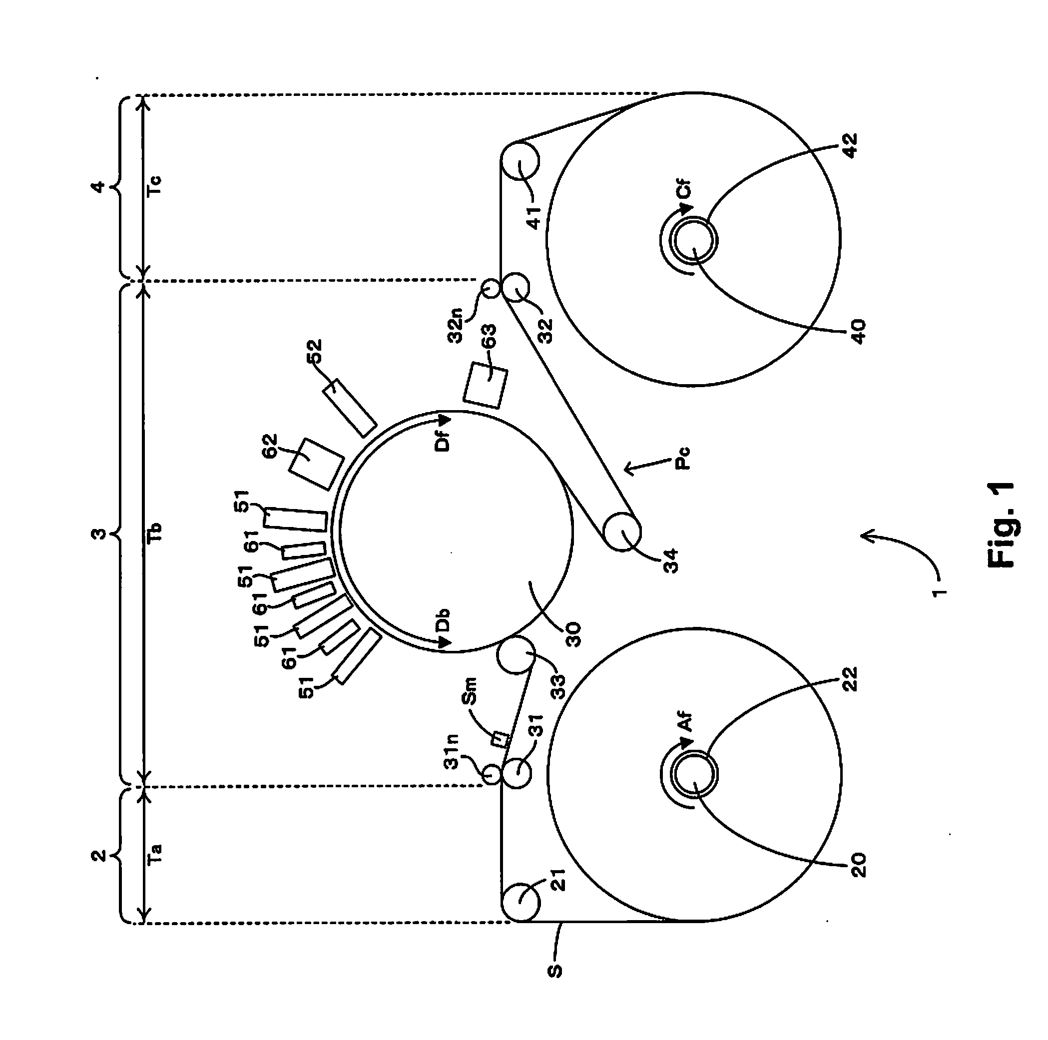
[0024]FIG. 1 is a front view schematically showing an example of a device constitution equipped with a printer capable of executing the present invention. As shown in FIG. 1, with the printer 1, one sheet S (web) for which both ends are wound in roll form on a delivery shaft 20 and a winding shaft 40 is stretched along a conveyance path Pc, and the sheet S undergoes image recording while being conveyed in a conveyance direction Df facing from the delivery shaft 20 to the winding shaft 40. The sheet S types are roughly divided into paper and film. To list specific examples, for paper, there is high quality paper, cast paper, art paper, coated paper and the like, and for film, there is synthetic paper, PET (polyethylene terephthalate), PP (polypropylene) and the like. Schematically, the printer 1 is equipped with a delivery part 2 (delivery area) that delivers the sheet S from the delivery shaft 20, a processing part 3 (processing area) that records an image on the sheet S delivered f...


PUM


Abstract

An image recording device includes a drive roller that conveys a recording medium by rotating, a driven roller that grasps the recording medium between it and the drive roller, a recording unit capable of recording an image on the recording medium arranged further to the downstream side than the drive roller in a first direction which is the recording media conveyance direction, and a control unit that records an image on the recording media while conveying the recording media in the first direction. The control unit, when the conveying of the recording media in the first direction stops, starts conveying the recording media in a second direction which is the reverse direction of the first direction, and stops conveying of the recording media in the second direction in a state with the image recorded on the recording media positioned between the drive roller and the driven roller.

Description

CROSS-REFERENCE TO RELATED APPLICATIONS[0001]This application claims priority to Japanese Patent Application No. 2014-044838 filed on Mar. 7, 2014. The entire disclosure of Japanese Patent Application No. 2014-044838 is hereby incorporated herein by reference.BACKGROUND[0002]1. Technical Field[0003]The present invention relates to an image recording device and an image recording method for conveying media while grasping the recording media with a drive roller and a driven roller.[0004]2. Related Art[0005]The printer of Japanese Unexamined Patent Publication No. 2013-116786 records an image on a sheet using a recording head arranged to the downstream side in the conveyance direction in relation to the drive roller while conveying the sheet in the conveyance direction by rotating a drive roller. In particular, this printer is equipped with a nip roller that grasps the sheet between it and the drive roller, and conveys the sheet while ensuring friction force between the drive roller an...

Claims


Application Information

Patent Timeline
IPC IPC(8): B41J13/00
CPCB41J13/0009B41J11/425B41J15/04
Inventor IMAMURA, ATSUSHITOYA, AKIHIRO
Owner SEIKO EPSON CORP
Why Eureka
Try Eureka