Ball-And-Socket Joint

a ball-and-socket joint technology, applied in the field of ballandsocket joints, can solve the problems of substantial deterioration of the service life of the spring element, and achieve the effect of reducing the number of requisite components and the structural size of the joint, and increasing the tension for

Active Publication Date: 2008-11-13
THK RHYTHM AUTOMOTIVE GMBH
View PDF16 Cites 5 Cited by
  • Summary
  • Abstract
  • Description
  • Claims
  • Application Information

AI Technical Summary

Benefits of technology

[0004]According to the invention, a ball-and-socket joint has a housing, a ball pivot with an essentially spherical bearing section that is mounted in the housing, a cover that is installed on the housing, and a spring element that has a support section and a spring section, the spring section lying radially outside of the support section and the spring element resting on the cover and on the bearing section. In an advantageous manner, such a ball-and-socket joint combines the upper bearing shell that is familiar from the state of the art and the spiral spring that serves to compensate for manufacturing tolerances and for wear that occurs during use so as to form one single component, namely, the spring element. This reduces the number of requisite components and the structural size of the joint. Another advantage ensues from the fact that the spring element rests on the cover, as a result of which a much higher tension force can be achieved than, for example, with a configuration having a spring element that is clamped on the edge by the cover.

Problems solved by technology

Consequently, a radial movement of the spring element is effectively prevented in case of an angular deflection of the ball pivot, which would otherwise lead to an excessive bending stress in the bending radius of the spring tongues and would thus substantially diminish the service life of the spring element.

Method used


Image

  • Ball-And-Socket Joint
  • Ball-And-Socket Joint
  • Ball-And-Socket Joint

Examples


Embodiment Construction

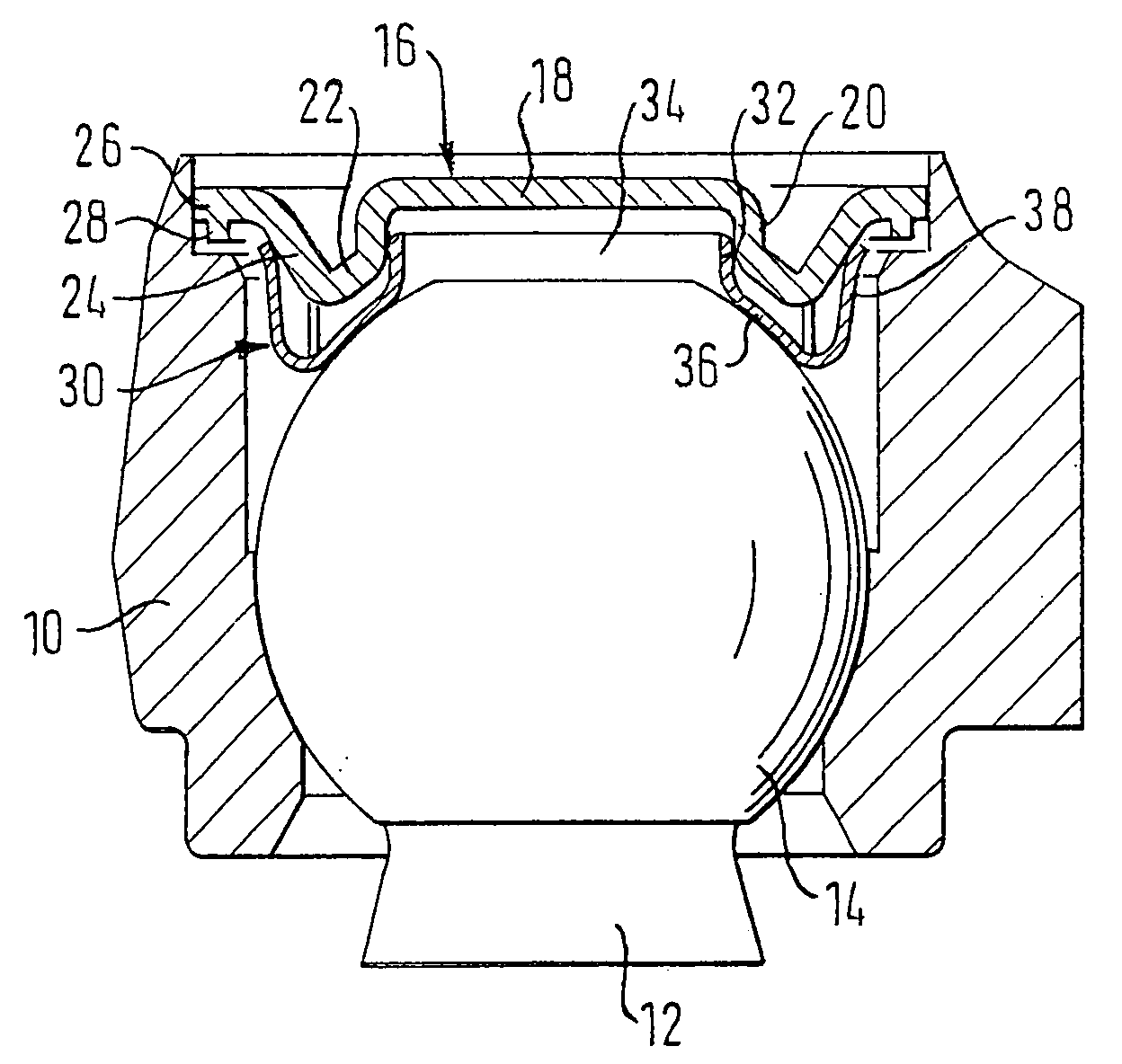
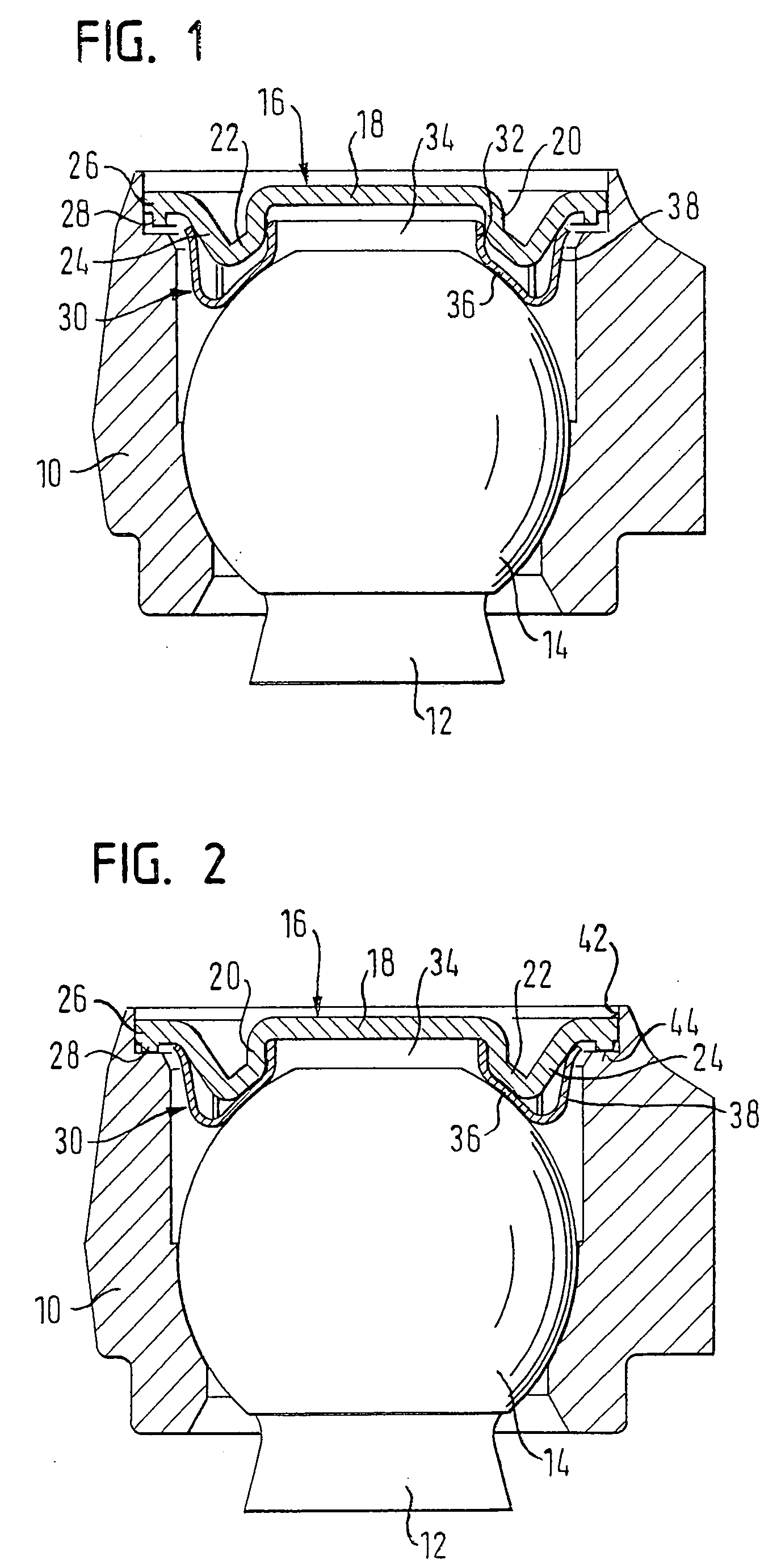
[0017]The ball-and-socket joint shown in FIG. 1 in a sectional view in the state before the installation of the cover comprises a housing 10 and a ball pivot 12 with an essentially spherical bearing section 14 that is mounted in the housing 10.

[0018]Moreover, there is a cover 16 that can be installed on the housing 10 and that, in a top view, is essentially circular. The cover 16 has a circular flat middle part 18 which is followed by a cylindrical guide surface 20 in the radial outward direction. Moreover, the cover 16 comprises an area 22 shaped like a spherical segment between two parallel circles and arranged outside of the cylindrical guide surface 20, an adjacent annular spreading section 24 that makes a transition to a likewise annular edge area 26, as well as a deformation rib 28 arranged on the edge area 26.

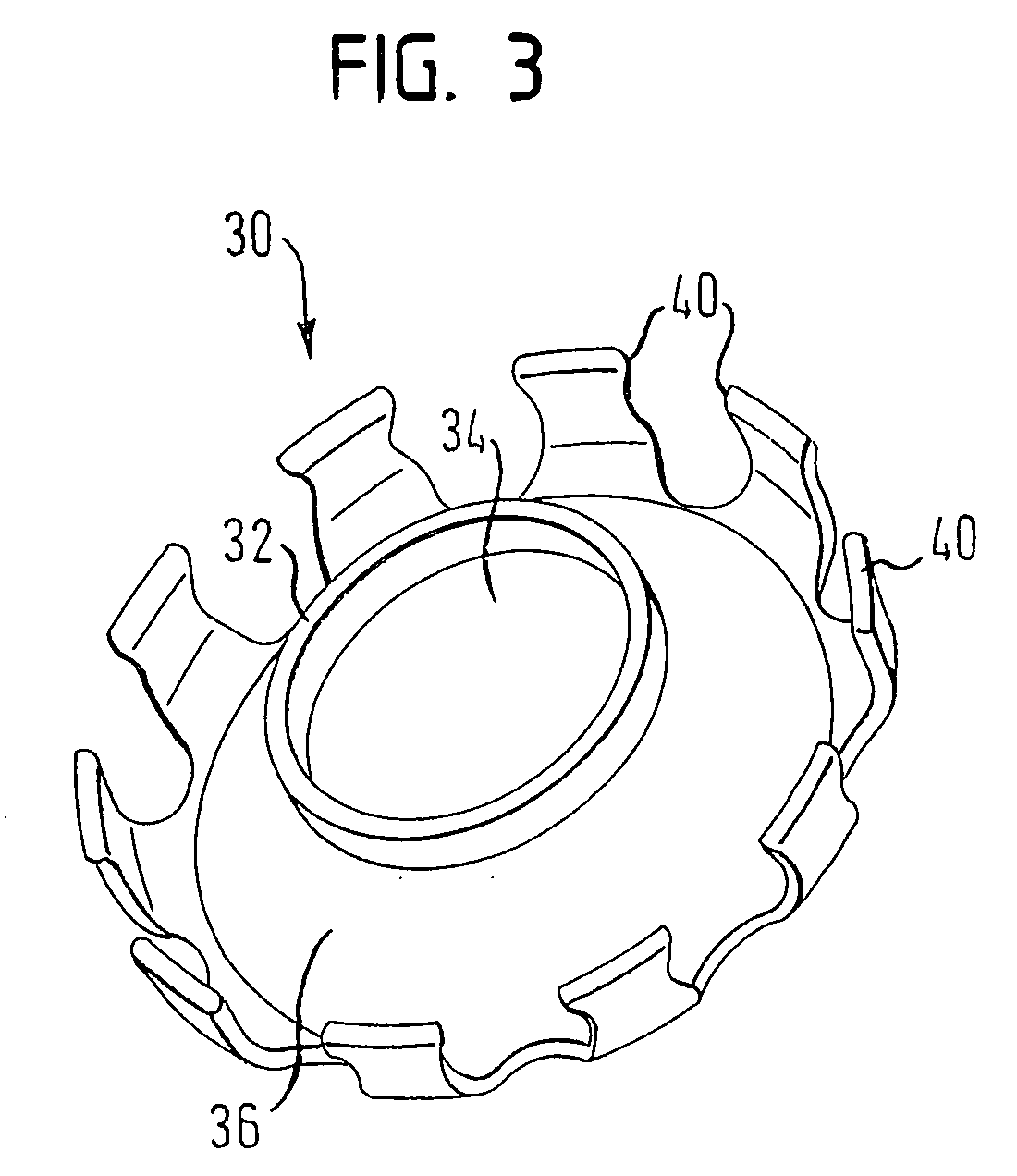
[0019]Between the cover 16 and the spherical bearing section 14, there is a spring element 30 that has a cylindrical holding section 32 encircling a circular opening 34 ...


PUM


Abstract

A ball-and-socket joint, especially for tie rods and steering rods of utility vehicles, has a housing, a ball pivot with an essentially spherical bearing section that is mounted in the housing, a cover that is installed on the housing, and a spring element that has a support section and a spring section. The spring section lies radially outside of the support section and the spring element rests on the cover and on the bearing section.

Description

CROSS-REFERENCE TO RELATED APPLICATIONS[0001]This application is a national stage of International Application No. PCT / EP2005 / 008730 filed Aug. 11, 2005, the disclosures of which are incorporated herein by reference in entirety, and which claimed priority to German Patent Application No. 20 2004 012 604.4 filed Aug. 11, 2004, the disclosures of which are incorporated herein by reference in entirety.BACKGROUND OF THE INVENTION[0002]The present invention relates to a ball-and-socket joint, especially for tie rods and steering rods of utility vehicles.[0003]Such ball-and-socket joints are known and, in addition to having a housing, a ball pivot with an essentially spherical bearing section that is mounted in the housing and a cover that is installed on the housing, they usually also have an upper bearing shell as well as a spiral spring that is arranged as a pressure spring between the cover and the upper bearing shell in order to keep the joint free of clearance. In the past, various ...

Claims


Application Information

Patent Timeline
Patent Type & Authority Applications(United States)
IPC IPC(8): F16C11/08B62D7/16F16C11/06
CPCB62D7/166Y10T403/32762F16C11/0647F16C11/0642F16C2326/24
Inventor ERDOGAN, CENGIZ
Owner THK RHYTHM AUTOMOTIVE GMBH
Why Eureka
Try Eureka