Transfer apparatus

Inactive Publication Date: 2008-11-13
DAIHEN CORP
View PDF12 Cites 15 Cited by
  • Summary
  • Abstract
  • Description
  • Claims
  • Application Information

AI Technical Summary

Benefits of technology

[0007]An object of the present invention, which is proposed under the circumstances described above, is to provide a transfer appar

Problems solved by technology

However, the conventional transfer apparatus may not stand the use to transfer a heated work in a vacuum in view of the thermal condition.
In this case, when the hand holds the heated w

Method used


Image

  • Transfer apparatus
  • Transfer apparatus
  • Transfer apparatus

Examples


Embodiment Construction

[0022]Preferred embodiments of the present invention will be described below with reference to the accompanying drawings.

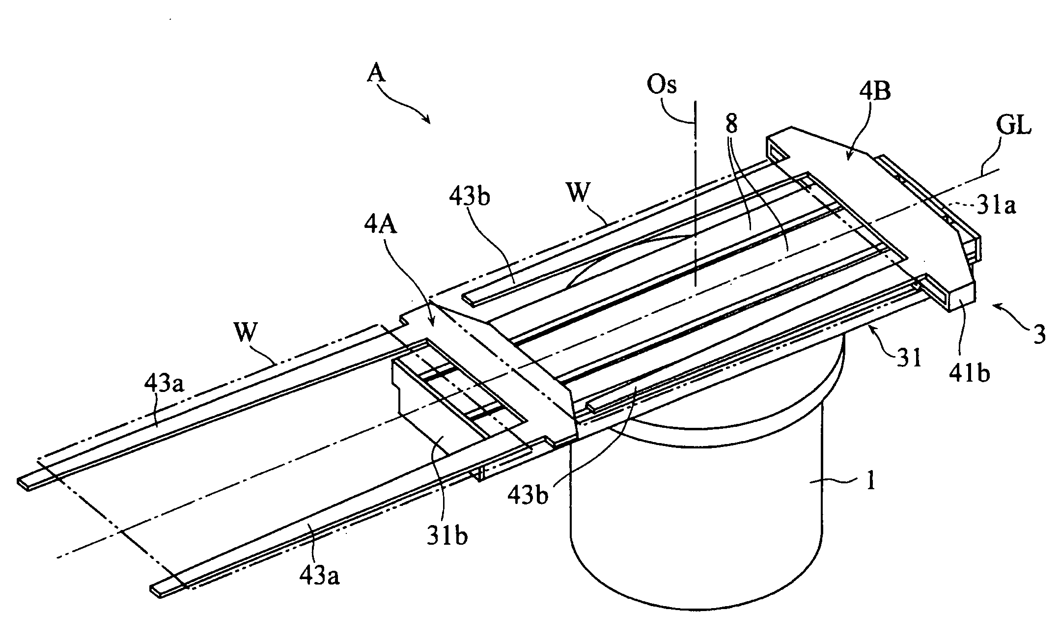
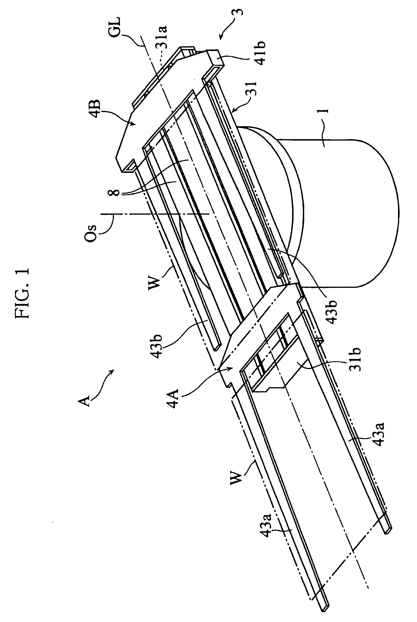
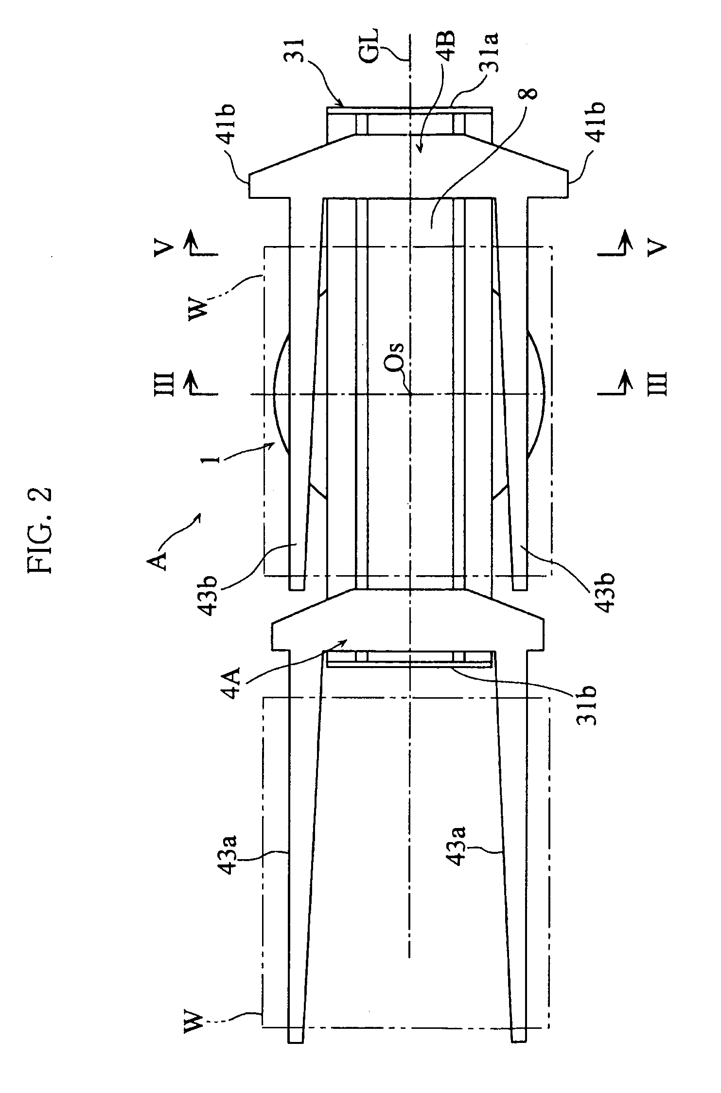
[0023]FIGS. 1-7 show a transfer apparatus according to a preferred embodiment of the present invention. The transfer apparatus A is used for transferring a work W in the form of a thin plate such as a substrate used for a liquid crystal display panel. As shown in FIGS. 1-3, the transfer apparatus A includes a stationary base 1, a swivel 2 supported by the stationary base 1 to be rotatable around a vertical rotation axis Os, a linear movement mechanism 3 supported by the swivel 2, and a pair of hands 4A and 4B individually supported by the linear movement mechanism 3. The hands 4A and 4B are configured to hold and carry the work W in a horizontal posture.

[0024]As shown in FIG. 3, the stationary base 1 includes a housing 1A having a generally columnar outer configuration made up of a bottom wall 11, a cylindrical side wall 12 and a top wall 13. The top wall 13 is fo...


PUM


Abstract

A transfer apparatus includes a stationary base, a swivel rotatably supported by the stationary base, and a linear movement mechanism supported by the swivel and including guide rails. Hands for carrying works are supported by the guide rails and movable along a horizontal straight travel path by the operation of the linear movement mechanism. A heat reflector is provided between the hands and the guide rails. A refrigerant circulation channel includes annular spaces for ensuring constant communication between a passage on the side of the stationary base and a passage on the side of the swivel. The refrigerant circulation channel includes cooling pipes held in contact with the heat reflector.

Description

BACKGROUND OF THE INVENTION[0001]1. Field of the Invention[0002]The present invention relates to a transfer apparatus for transferring a work such as a thin plate. In particular, the present invention relates to a transfer apparatus suitable for transferring a heated work in a vacuum.[0003]2. Description of the Related Art[0004]An example of transfer apparatus for transferring a work in the form of a thin plate in a vacuum is described in JP-A-2005-125479. As shown in FIGS. 17-25 of this Japanese patent document, the transfer apparatus includes a pair of link arm mechanisms provided on a swivel. Each of the link arm mechanisms includes an end provided with a hand for horizontally holding a work in the form of a plate such as a glass substrate for a liquid crystal display panel. When a swivel rotates around a rotation axis on a stationary base, the paired link arm mechanisms rotate correspondingly. When the link arm mechanism is driven, the work held by the hand moves linearly within...

Claims


Application Information

Patent Timeline
IPC IPC(8): H01L21/67
CPCH01L21/67742H01L21/68707
Inventor URATANI, TAKAFUMISADO, DAISUKEMATSUO, HIDEKI
Owner DAIHEN CORP
Why Eureka
Try Eureka