Battery pack

a battery pack and battery technology, applied in the field of batteries, can solve problems such as reducing output power, and achieve the effect of preventing the reduction of the performance of the battery pack in us

Inactive Publication Date: 2008-11-13
SANYO ELECTRIC CO LTD
View PDF13 Cites 106 Cited by
  • Summary
  • Abstract
  • Description
  • Claims
  • Application Information

AI Technical Summary

Benefits of technology

[0009]The present invention has been made with a view to overcome the drawbacks found in the conventional types of battery packs as described above. It is the primary object of

Problems solved by technology

Thus, the drawback is eliminated that an expansion of the electrode

Method used


Image

  • Battery pack
  • Battery pack
  • Battery pack

Examples


Embodiment Construction

)

[0055]In a main though non-exclusive application, the battery pack of the present invention is suitable for a power supply unit that is mounted to an electric vehicle such as a hybrid car and an electric automobile so that electric power is supplied to a driving motor to drive the vehicle.

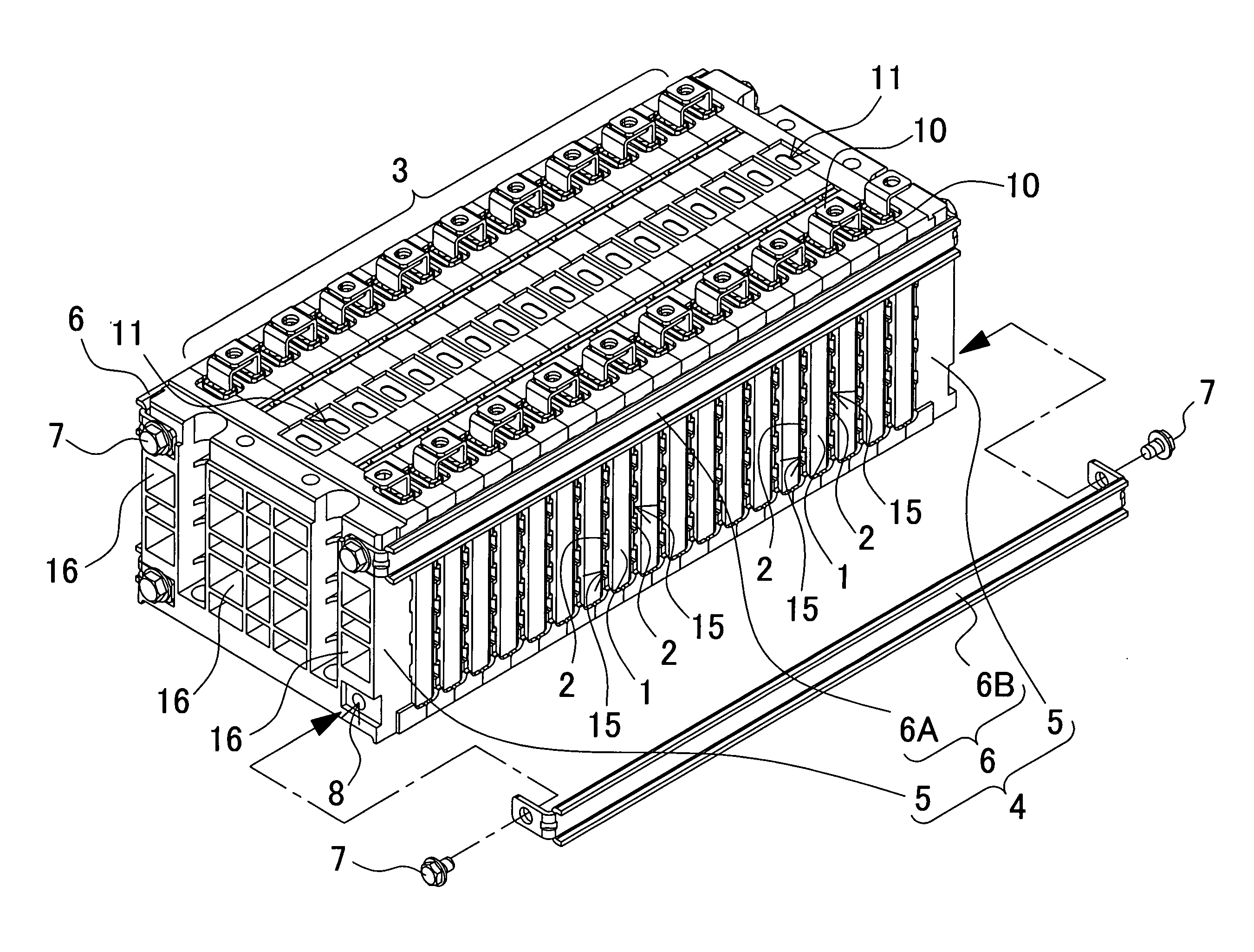
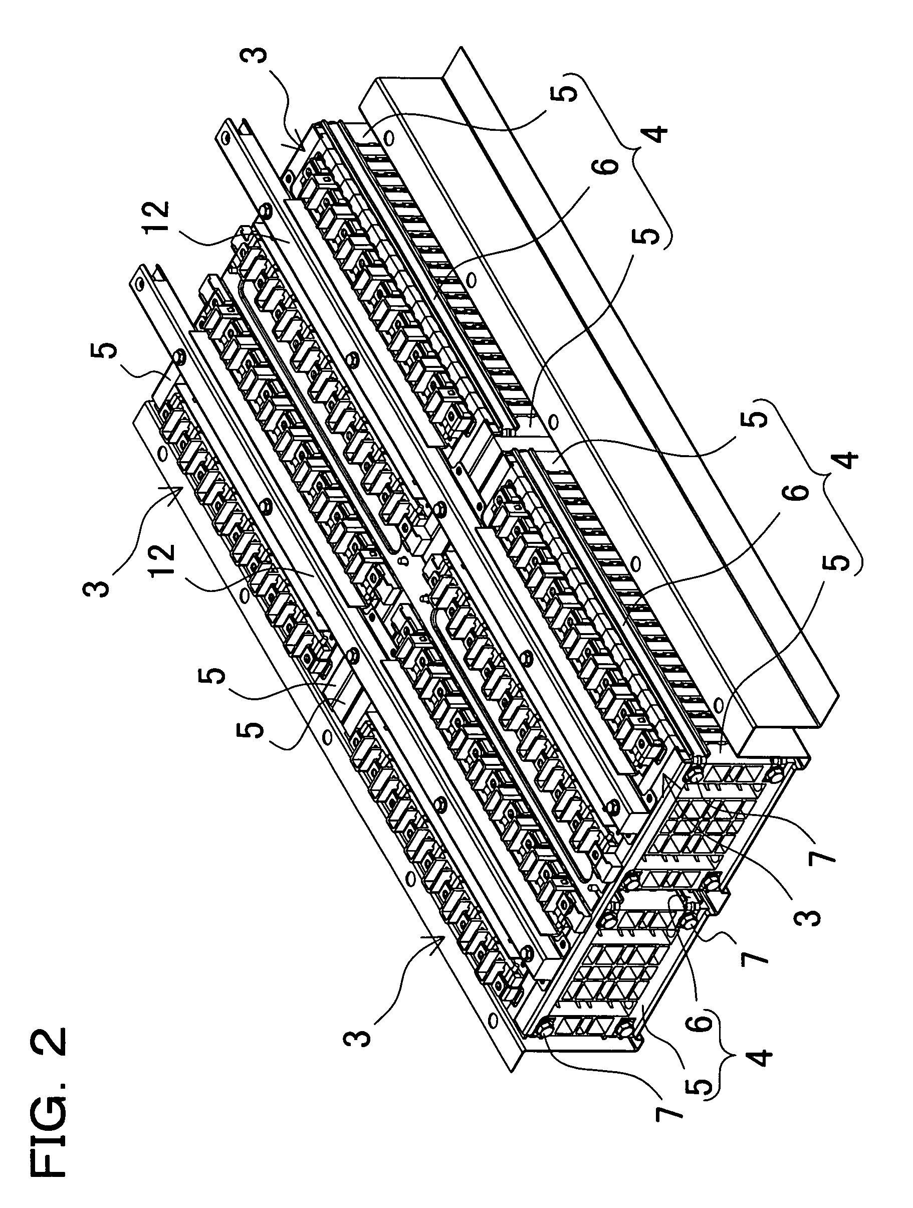
[0056]FIG. 2 through FIG. 4 are views showing the battery pack in accordance with an embodiment of the present invention. FIG. 2 and FIG. 3 show a power supply unit provided with four units of battery packs, the power supply unit being used for a vehicle, while FIG. 4 is a perspective view of the battery pack that is to be incorporated in such power supply units. Further, FIG. 5 through FIG. 25 show the battery packs in accordance with alternative embodiments of the invention. However, in FIG. 5 through FIG. 25 respectively, a safety valve provided to the rectangular cells is not shown, for the purpose of simplifying the drawings.

[0057]The battery packs shown in these drawings respectively include...


PUM


Abstract

The battery pack includes a battery block in which a plurality of electric cells being rectangular cells are layed, and a fixture component for fixing the electric cells in the battery block. The fixture component includes a pair of end plates disposed on opposite side faces of the layered rectangular cells, and a metal strap with which the layered rectangular cells are fixed in their compressed state by connecting the tip of the metal strap to the end plate.

Description

BACKGROUND OF THE INVENTION[0001]1. Field of the Invention[0002]The present invention relates to a battery pack in which a plurality of rectangular cells are layered and fixed by means of a fixture component.[0003]2. Description of the Related Art[0004]A battery pack, in which a plurality of rectangular cells are layered, is described in Japanese Utility Model Publication H3-32364-U (1991); and in such battery pack, a pair of end plates 905 are connected by means of a bolt 906 and the layered electric cells 901 are disposed between the end plates 905, as shown in FIG. 1.[0005]In the battery pack of Japanese Utility Model Publication H3-32364-U (1991) as shown in FIG. 1, an auricular projection 908 is provided, at opposite sides of the end plate 905, for allowing the bolt 906 to be inserted through for connection of the bolt 906. The bolt 906 is inserted through the auricular projection 908, and a nut 907 is screwed onto a tip of the bolt to fix the end plate 905. Such structured bat...

Claims


Application Information

Patent Timeline
IPC IPC(8): H01M2/10H01M10/60H01M10/613H01M10/617H01M10/625H01M10/647H01M10/6557H01M10/6563H01M50/209H01M50/264H01M50/289
CPCH01M2/1077H01M6/42H01M10/052H01M10/058Y02E60/122Y02T10/7011Y02E60/10H01M50/209H01M50/264H01M50/289Y02T10/70
Inventor OKADA, WATARU
Owner SANYO ELECTRIC CO LTD
Why Eureka
Try Eureka