Endoscopic instrument

a technology of endoscopic instruments and projection lengths, applied in the field of endoscopic instruments, can solve the problems of difficult to reliably obtain desirable projection lengths, inability to easily adjust the projection length of the incising section of the aforementioned instruments, and difficulty in reliably obtaining desired projection lengths. achieve the effect of easy and reliable adjustmen

Active Publication Date: 2008-11-13
OLYMPUS CORP
View PDF1 Cites 8 Cited by
  • Summary
  • Abstract
  • Description
  • Claims
  • Application Information

AI Technical Summary

Benefits of technology

[0018]The endoscopic instrument according to the present invention can easily and reliably adjust and maintain two or more stepwise projection length of the incising section relative to a sheath. Therefore, intervention corresponding to the shape of object tissue can be conducted by desirably adjusting the projection length of the knife 2.

Problems solved by technology

Projection length, which is generally short, of the incising section of the aforementioned instrument cannot be adjusted easily.
The above method is difficult to reliably obtain desirable projection length since generally the projection length is subject to small pitch, e.g., 0.5 mm etc.

Method used


Image

  • Endoscopic instrument
  • Endoscopic instrument
  • Endoscopic instrument

Examples


first embodiment

[0032]An endoscopic instrument (simply hereinafter called an instrument) according to the present invention will be explained with reference to FIGS. 1 to 6.

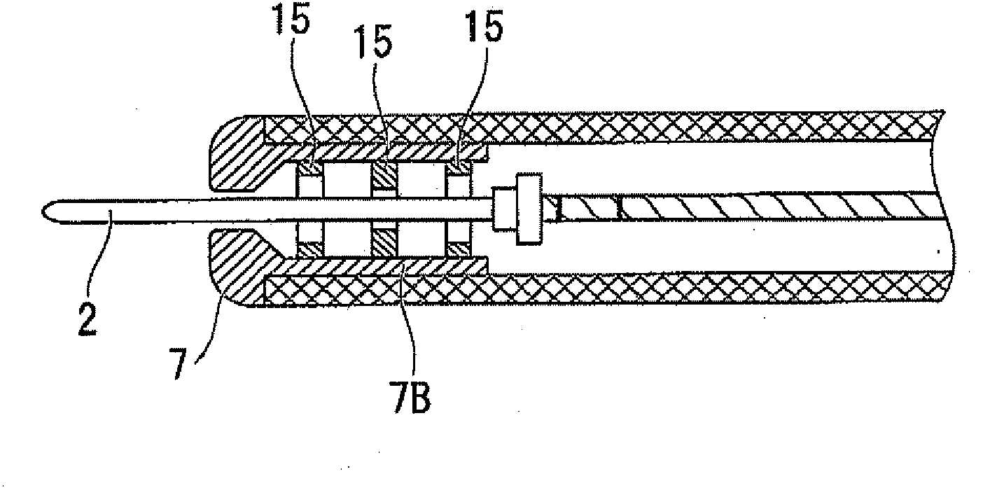
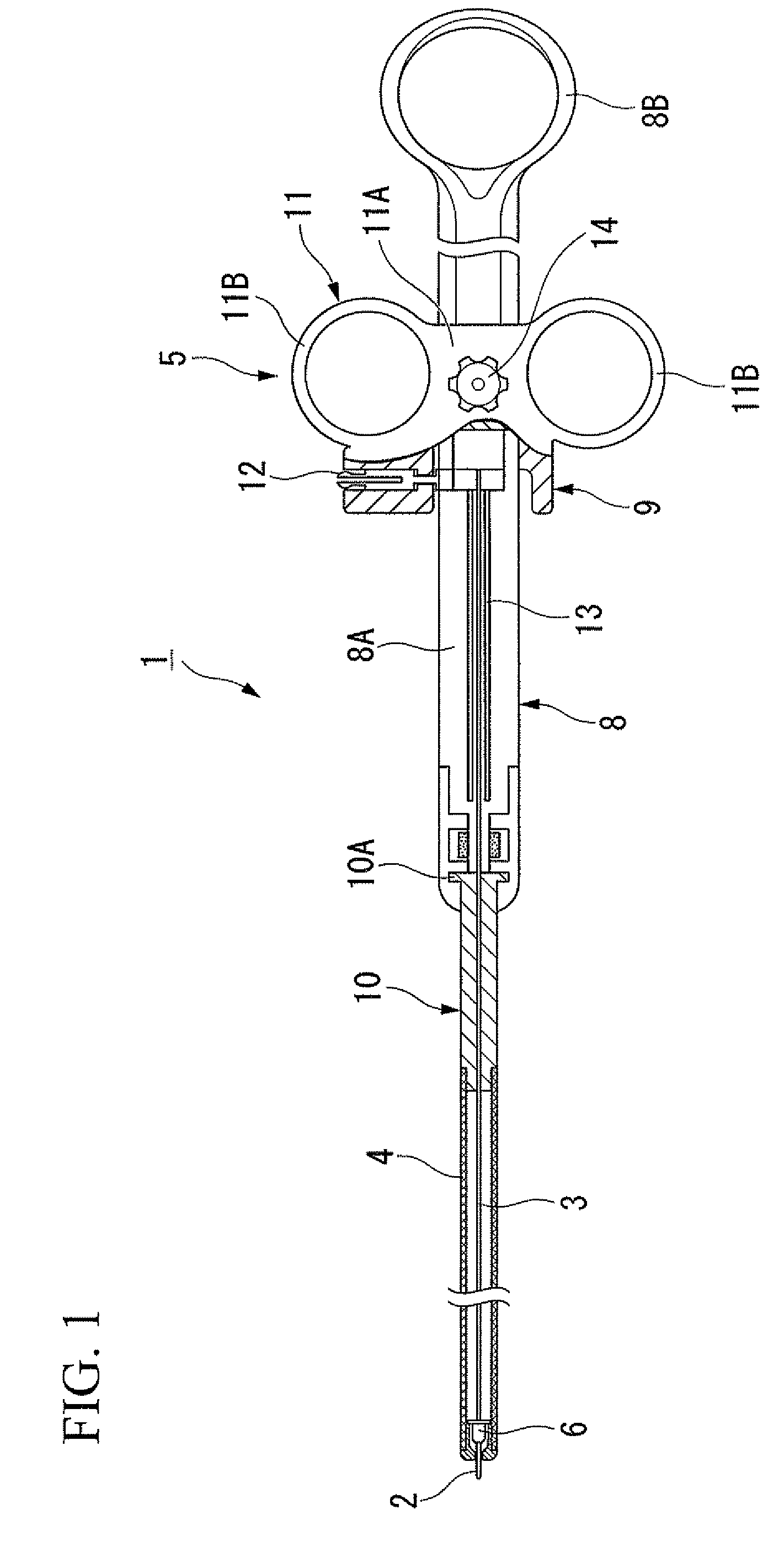
[0033]FIG. 1 is a cross-sectional view showing an instrument 1 of the present embodiment. The instrument 1 includes a wire 3 having a high-frequency knife (incising section) 2 attached to the distal end thereof; a sheath 4 that covers the outer periphery of the wire 3; and a maneuvering section 5 for maneuvering the wire 3 and the sheath 4.

[0034]The high-frequency knife (simply hereinafter called knife) 2 made of a metal bar having a length of 3 mm etc. is subject to high-frequency power supply to carry out incisional intervention for coelomic tissue as explained later. The knife 2 may be a pad shape or a hook shape in place of a bar shape.

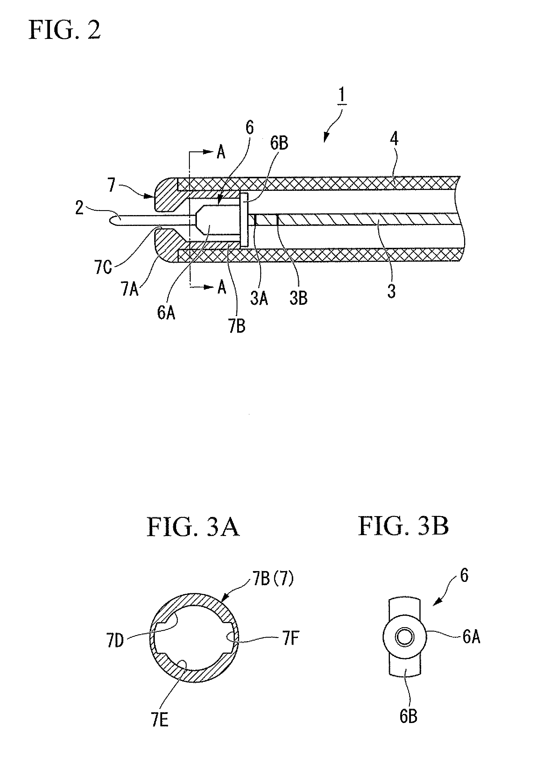
[0035]FIG. 2 is an enlarged view of the vicinity of the distal end of the instrument 1. The wire 3 made of metal having superior torque transmissibility, e.g., stainless steel is inserted thro...

second embodiment

[0058]An instrument according to the present invention will be explained next with reference to FIGS. 7 and 8.

[0059]The difference of an instrument 21 according to the present embodiment from the endoscopic instrument 1 of the aforementioned first embodiment is based on a fact that a distal end member and a stopper have engageable female and male screw threads formed thereon.

[0060]Note that components that are in common with those of the aforementioned instrument 1 will be assigned the same numeric symbol and redundant explanation thereof will be omitted.

[0061]FIG. 7 is an enlarged view of the vicinity of the distal end of the instrument 21. A stopper 22 of the instrument 21 free from a flange section is a cylinder substantially. A distal end member (screwing member) 23 has a disk section 23A and a cylindrical section 23B similarly to the distal end member 7 of the first embodiment. The cylindrical section 23B is provided with a screw groove 21C formed on the inner periphery surface...

third embodiment

[0069]An instrument according to the present invention will be explained next with reference to FIGS. 9 and 10. Difference of an instrument 31 according to the present embodiment from the aforementioned endoscopic instrument 1 is based on the shape of a distal end member and shape of a stopper.

[0070]Note that components that are common with those of the aforementioned instrument 1 will be assigned the same numeric symbol and redundant explanations thereof will be omitted.

[0071]FIG. 9 is an enlarged view of the vicinity of the distal end of the instrument 31. Provided to a stopper 32 of the instrument 31 is a distally projecting abutment section 32A. Provided to the proximal end of a disk section 33A of a distal end member 33 are three abutment surfaces making contact with the abutment section 32A to regulate distal sliding movement of the wire 3.

[0072]FIG. 10 is a schematic view showing the shape of the disk section 33A of the distal end member 33. Note that, a cylinder section 33B ...


PUM


Abstract

An endoscopic instrument includes: a knife; a wire having a distal end connected to the knife; a sheath allowing the wire to pass therethrough; a main body having the freely rotative sheath fixed thereto; a slider, having the wire fixed thereto, disposed slidable in an axial line direction of the main body; a stopper, provided to the wire or the knife, for projecting outward radially relative to the wire; a first-distal-regulation section and a second-distal-regulation section provided to the sheath for regulating distal sliding movement of the wire by making contact with the stopper; and a second-distal-regulation section, provided distally relative to the first-distal-regulation section, for regulating distal sliding movement of the wire by making contact with the stopper, wherein the stopper is capable of moving between the first-distal-regulation section and the second-distal-regulation section by rotating the main body relative to the sheath around an axial line by predetermined rotational angle, and at least two different projection lengths of the knife can be maintained by contacting the main body to the first-distal-regulation section or the second-distal-regulation section. Accordingly, at least two stepwise adjustment of the projection length of the incising section can be maintained easily and reliably.

Description

BACKGROUND OF THE INVENTION[0001]1. Field of the Invention[0002]The present invention relates to an endoscopic instrument inserted into an operation channel of an endoscopic apparatus.[0003]The present application claims priority to Japanese Patent Application No. 2007-122524 filed May 7, 2007, the content of which is incorporated herein by reference.[0004]2. Background Art[0005]Conventionally known instruments, e.g., needle knives for endoscopic insertion use into body cavity incise mucosa etc. using high-frequency electric current (see Japanese Unexamined Utility Model (Registration) Application Publication No. S61-191012, hereinafter called Patent Document 1). Instruments of this type have an incising section, e.g., an interventional needle knife on a distal end of a wire inserted into an insulative sheath inserted through all endoscope channel. The incising section is capable of freely projecting or retracting relative to the distal end of the sheath by maneuvering a maneuvering...

Claims


Application Information

Patent Timeline
Patent Type & Authority Applications(United States)
IPC IPC(8): A61B1/018
CPCA61B18/1477A61B18/1492A61B2018/1425A61B17/00
Inventor NAKAMURA, TSUTOMUSUZUKI, KEITAMUYARI, YUTAMOTOSUGI, SHUNSUKE
Owner OLYMPUS CORP
Why Eureka
Try Eureka