Joining Element

Active Publication Date: 2008-11-13
DEPUY SYNTHES PROD INC
View PDF49 Cites 72 Cited by
  • Summary
  • Abstract
  • Description
  • Claims
  • Application Information

AI Technical Summary

Benefits of technology

[0012]In packagings and containers for goods, ropes having the features of the invention can ensure that the packaging remains securely held by the surrounding ropes, despite the effects of weather.
[0013]The invention permits the use of a method for stimulating healing and for stimulating biological transformation and regeneration p

Problems solved by technology

In particular, the swelling of a core material in the first material can enforce a change in shape, for examp

Method used


Image

  • Joining Element
  • Joining Element
  • Joining Element

Examples


Embodiment Construction

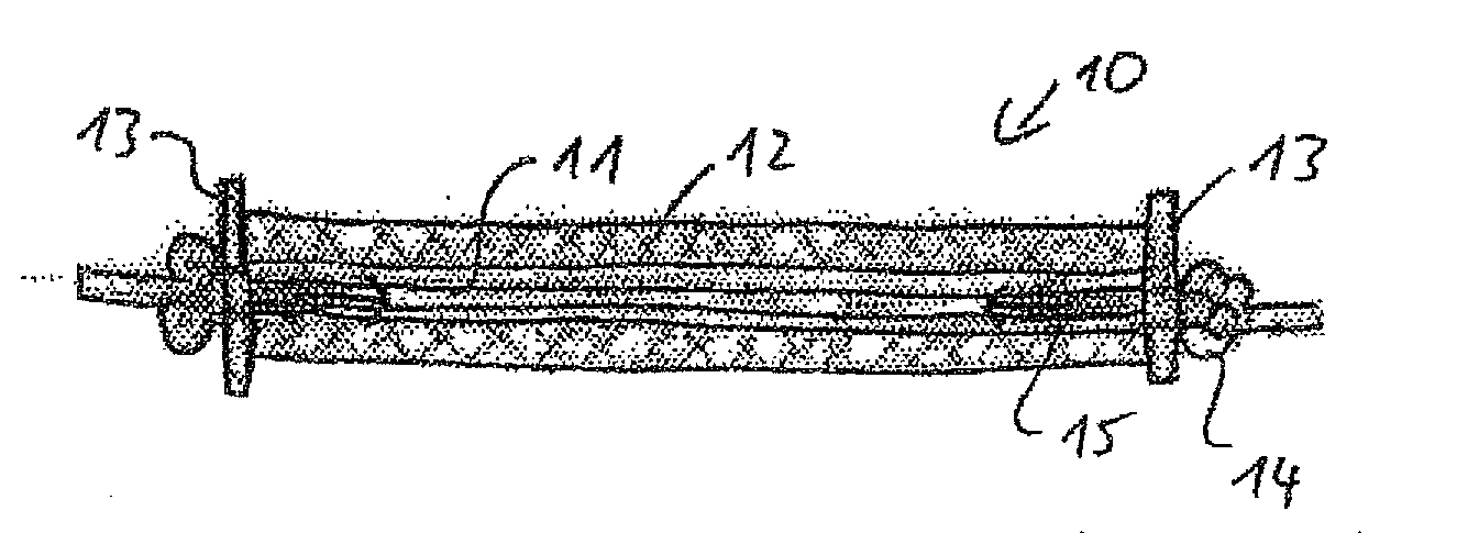
[0037]FIG. 1 shows a schematic representation of a part 10 of a joining element, which comprises a pretensioned core 11 surrounded by a jacket 12. The jacket 12 is composed of a rigid material, which is compressed under the effect of chemical and physical processes that take place over the course of time and are described below. The resulting force that triggers this compression process is the force resulting from the pretensioning of the core minus the tensioning force acting on the thread from the environment (for example the tensioning force applied during stitching). As the tensioning force exerted on the thread by the environment decreases, the resulting compressive force acting on the jacket increases. This favors the compression of the jacket, resulting in an accelerated contraction of the thread or of the textile structure formed from the latter. This results in a tensioning of the thread or of the textile structure until an equilibrium is once again established between the ...


PUM

PropertyMeasurementUnit
Lengthaaaaaaaaaa
Osmotic pressureaaaaaaaaaa
Force constantaaaaaaaaaa

Abstract

Disclosed is a joining element (10), especially a suture material for surgical use. Said joining element (10) is composed of a first material (12) that is essentially rigid during impingement by a relatively short-lasting tensile load on opposite sides as well as a second material (11) which is connected to the first material. The second material is substantially rigid during impingement by said tensile load on opposite sides while contracting slowly during a second period of time that is longer than the first period of time.

Description

TECHNICAL FIELD OF THE INVENTION[0001]The invention relates to a joining element, especially a suture material, especially for surgical purposes, but also relates to a two-dimensional or three-dimensional textile structure, especially also for technical use for joining technical structures, for example.PRIOR ART[0002]In the event of ligaments or tendons rupturing, a problem that still remains largely unresolved is that of securing a tendon for example to a bone in such a way that the connection does not come loose under the effect of loading. One of the problems is that the loads that are exerted on a joining element between bone and tendon are very different. Over long periods of time it is desirable for the joining element to contract, that is to say for the joining element between bone and tendon to tension. It is also possible to have a system with a high degree of damping. Movements on the part of the patient may subject the joining element to rapidly increasing high loads, und...

Claims


Application Information

Patent Timeline
IPC IPC(8): A61B17/04
CPCA61L17/00A61B17/04A61B17/06166B29C61/0608
Inventor MAYER, JORGGANZ, JOCHENKELLER, BEATHERTEL, RALPH
Owner DEPUY SYNTHES PROD INC
Why Eureka
Try Eureka