Stirling cycle cryogenic cooler with dual coil single magnetic circuit motor

a technology of magnetic circuit motor and stirling cycle, which is applied in the field of cryogenic coolers, can solve the problems of increased system mass and volume, inability to activate control, and high cost of stirling cryocooler efficiency and operational flexibility,

Active Publication Date: 2008-11-20
RAYTHEON CO
View PDF9 Cites 9 Cited by
  • Summary
  • Abstract
  • Description
  • Claims
  • Application Information

AI Technical Summary

Benefits of technology

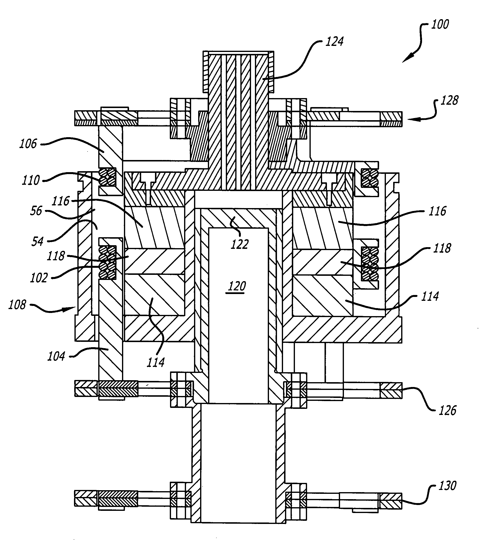
[0015]Hence, the invention provides a method and mechanism for eliminating one of the magnetic circuits in a conventional Stirling cryocooler. A single magnetic circuit is used to drive both of the necessary separately moving coils (compressor and displacer). Inasmuch as the bulk of motor mass is due to the magnetic circuit, the total motor mass for this type of Stirling-cryocooler should be only slightly more than that of a typical comparable pulse-tube cryocooler.

Problems solved by technology

The magnetic circuits are typically very heavy due to their composition of steel and rare earth magnets.
Pulse tubes rely on purely passive means to control this phase angle such that no active control is possible.
The efficiency and operational flexibility of the Stirling cryocooler comes at the cost of increased system mass and volume, parameters that many applications are extremely sensitive to.
Hence, although Stirling-class cryocoolers are generally more efficient and operationally flexible (efficient over a much wider range of operating conditions) than pulse-tube cryocoolers, their increased mass and volume lessen their appeal in many applications.
However, this scheme has a serious drawback of its own: the lack of a Stirling displacer piston motor precludes any type of active control of the displacer piston.
Hence, passive-displacer Stirling cryocoolers are often ill suited for use.
While sound mechanical and packaging design practices have been used to help minimize the penalty, Stirling-class cryocoolers are generally much heavier and more voluminous than comparable capacity pulse-tube cryocoolers.

Method used


Image

  • Stirling cycle cryogenic cooler with dual coil single magnetic circuit motor
  • Stirling cycle cryogenic cooler with dual coil single magnetic circuit motor
  • Stirling cycle cryogenic cooler with dual coil single magnetic circuit motor

Examples


Embodiment Construction

[0024]Illustrative embodiments and exemplary applications will now be described with reference to the accompanying drawings to disclose the advantageous teachings of the present invention.

[0025]While the present invention is described herein with reference to illustrative embodiments for particular applications, it should be understood that the invention is not limited thereto. Those having ordinary skill in the art and access to the teachings provided herein will recognize additional modifications, applications, and embodiments within the scope thereof and additional fields in which the present invention would be of significant utility.

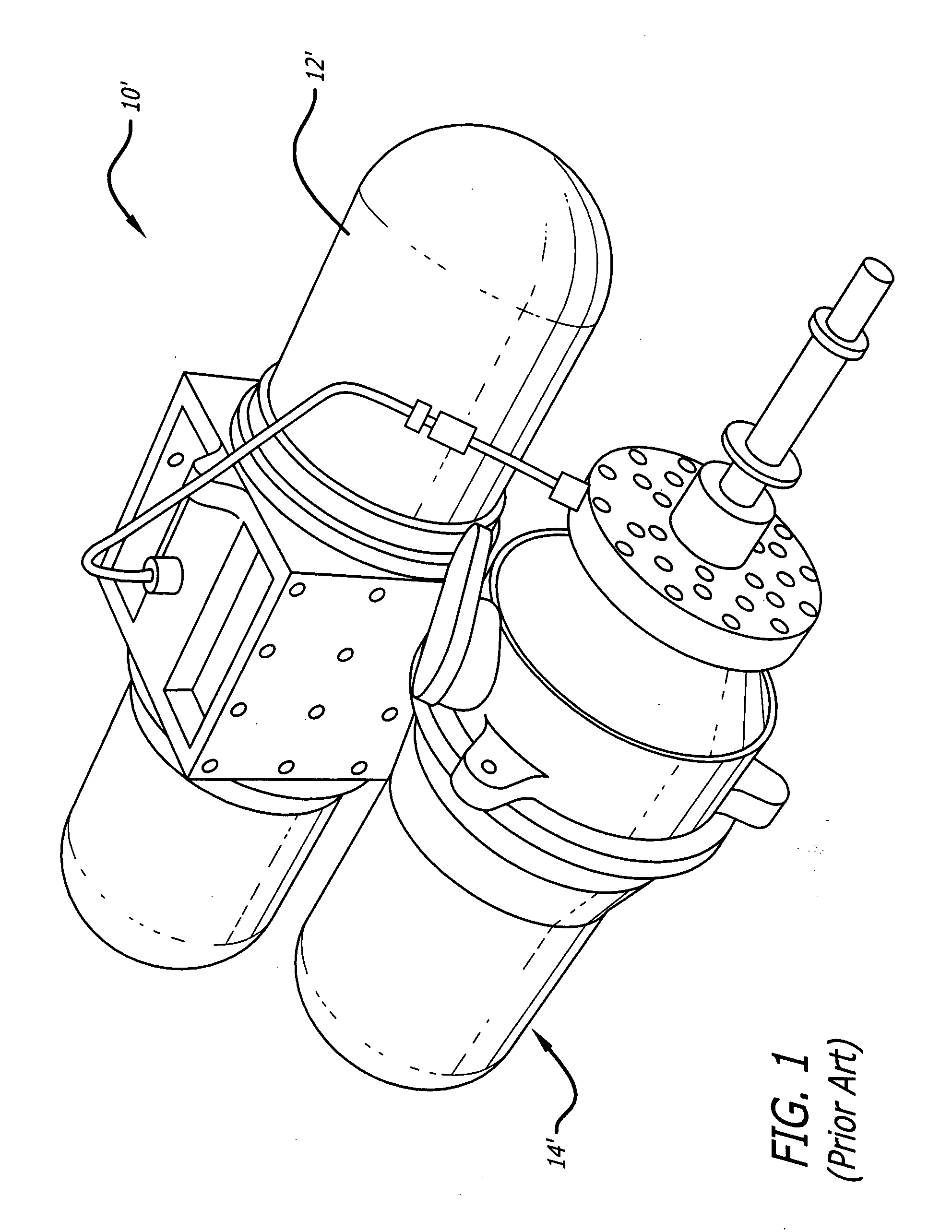
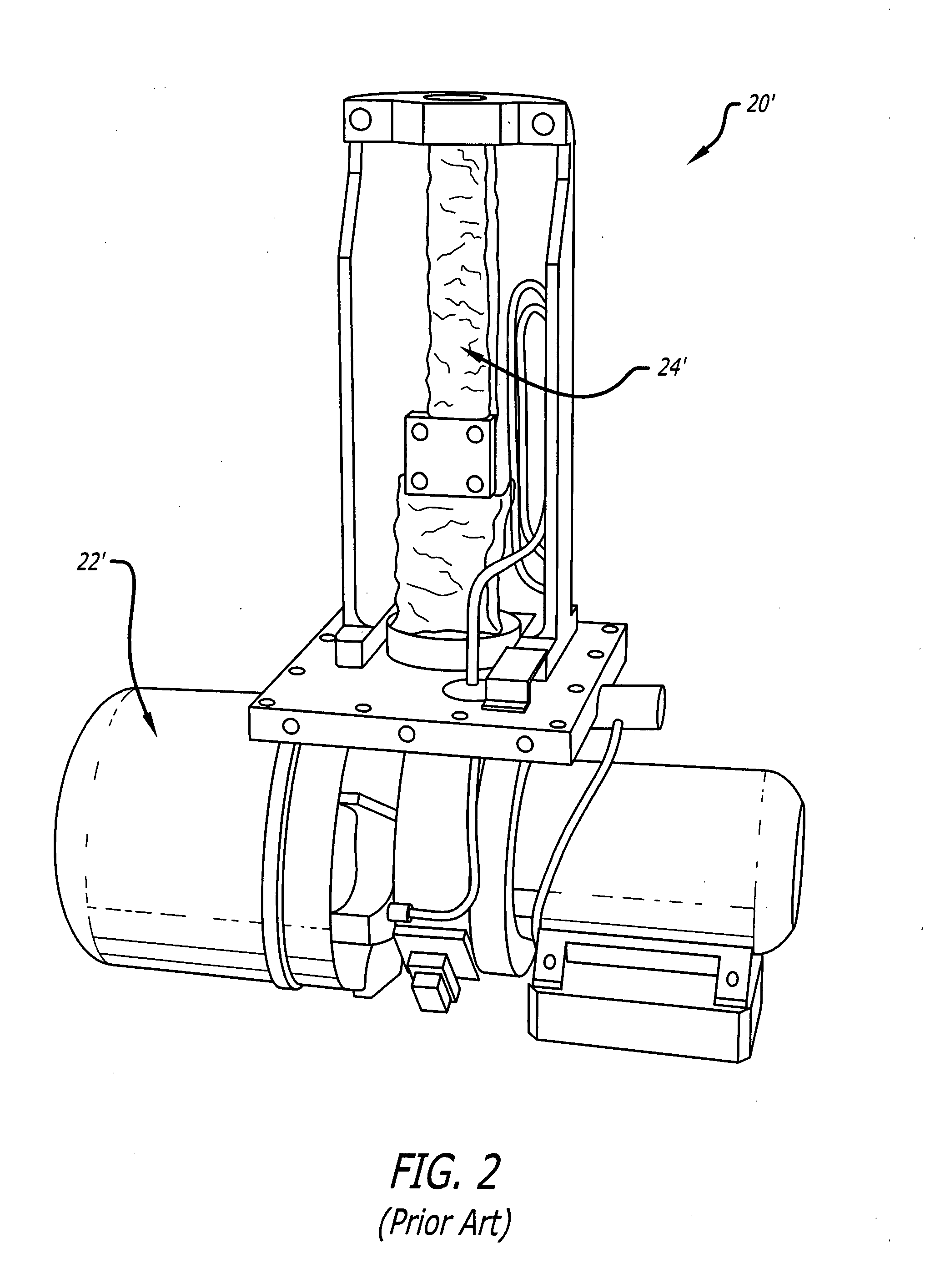
[0026]FIG. 1 is a perspective view of a typical two-module Stirling-cycle cryocooler implemented in accordance with conventional teachings. As illustrated in FIG. 1, a typical Stirling-class cryocooler 10′ is typically composed of two separate modules. The first module is a compressor module 12′. This module typically contains one or more internal, l...


PUM


Abstract

A method and mechanism for eliminating one of the magnetic circuits in a conventional two motor Stirling cryocooler. The inventive cooler is a Stirling cycle cryogenic cooler with a magnetic circuit for generating a field of magnetic flux in two separate magnetic gaps; a first coil disposed in the flux field of one gap; and a second coil disposed in the flux field of the second gap. The second coil is mounted for independent movement relative to the first coil. In a specific embodiment, the first coil is a compressor coil and the second coil is a displacer coil. The coils are energized with first and second variable sources of electrical energy in response to signals from a controller.

Description

BACKGROUND OF THE INVENTION[0001]1. Field of the Invention[0002]The present invention relates to cryogenic coolers. More specifically, the present invention relates to linear Stirling cycle cryogenic coolers.[0003]2. Description of the Related Art[0004]For certain applications, such as space infrared sensor systems, a cryogenic cooling subsystem is required to achieve improved sensor performance. Numerous types of cryogenic cooling subsystems are known in the art, each having relatively strong and weak attributes relative to the other types. Stirling and pulse-tube linear cryocoolers are typically used to cool various sensors and focal plane arrays in military, commercial, and laboratory applications. Both types of cryocoolers use a linear-oscillating compressor to convert electrical power to thermodynamic PV power. The implementation of the compression / expansion cooling cycle differs between the two and each type has advantages and disadvantages that make one or the other ideal for...

Claims


Application Information

Patent Timeline
Patent Type & Authority Applications(United States)
IPC IPC(8): F25B21/02F25B19/00
CPCF25B9/14F25B2309/001F25B9/00F25B21/00F25B2321/0021
Inventor HON, ROBERT C.BELLIS, LOWELL A.YONESHIGE, CYNDI H.
Owner RAYTHEON CO
Why Eureka
Try Eureka