Reinforced axillary crutch with adjustable handgrip

a technology of axillary crutches and handgrips, which is applied in the field of axillary crutches, can solve the problems of increasing the cost of making such crutches, compromising the structural strength of the shafts at such locations, and prone to bending or even breaking conventional axillary crutches, so as to enhance the assembly and reinforce the shafts. the effect of strength

Inactive Publication Date: 2008-11-20
WENG KUAN JEN
View PDF22 Cites 3 Cited by
  • Summary
  • Abstract
  • Description
  • Claims
  • Application Information

AI Technical Summary

Benefits of technology

[0006]In order to reinforce the strength of the shafts in the axillary crutch and enhance the assembly between the handgrip and the shafts, a reinforced axillary crutch with adjustable handgrip is disclosed in the invention. The axillary crutch includes two opposite shafts that make up a body, and the shafts are formed with a connecting portion in the center and a slit in a lateral side, respectively, and a wall portion provided with a plurality of positioning holes is embedded between the sliding grooves provided at two inner lateral walls of each shaft; each positioning hole has a wider upper opening and a narrower lower opening.
[0008]Therefore, a fortified wall portion is fitted into the shafts that make up the body of the axillary crutch before being bent into a predetermined shape together and secured in the shafts. The shafts are not formed with any thru openings, and thus are not compromised in terms of structural strength. In other words, the structure of the shafts remains complete, which significantly increases the ability of the shafts for holding heavier loads.
[0009]Furthermore, the two ends of the pivot fitted through the handgrip not only hold the two shafts together, but also prevent the two shafts from buckling outwards; while the protrusions on the extended portions at both ends of the handgrip may be fitted into the positioning hole to ensure the handgrip is securely positioned and protected from loosening.

Problems solved by technology

However, to allow the position of the handgrip to be adjusted according to the length of a user's arm, a plurality of openings are formed on the shafts for screw joints and butterfly nuts to fit into, but this also compromises the structural strength of the shafts at such locations, even though the handgrip is where the greatest force is exerted upon the whole axillary crutch.
As a result, the conventional axillary crutches are prone to bending or even breaking because the opening of holes thereon renders the crutches unable to withhold a strong exerted force.
The common solution is to make the walls of the shafts thicker, though this also increases the cost for making such crutches.
Although the damage from the formation of thru openings to the structural strength of the shafts is reduced as a consequence, the structure of the handgrip also becomes more complicated and vulnerable, which means the shafts and the handgrip are more difficult to make and assemble, and the shafts and the handgrip are also more difficult to disassemble and maintain in case of breakage.
Further, the assembly of all of the components of the aforesaid axillary crutch requires the use of rivets, which are not only more laborious but also require more components (such as rivets, nails, or screws) for the assembly thereof, and this in turn compromises the structural strength of the axillary crutch.
However, even though the position of the handgrip may be adjusted by inserting or removing a pivot protruding from the plugs at both ends of the handgrip into the positioning holes on the shafts, the pivot cannot restrain the two shafts when a force is exerted upon both shafts, and thus the shafts may easily buckle or twist outwards, which subsequently causes the pivot of the plugs become loosened from the positioning hole and possible injure the users.

Method used


Image

  • Reinforced axillary crutch with adjustable handgrip
  • Reinforced axillary crutch with adjustable handgrip
  • Reinforced axillary crutch with adjustable handgrip

Examples


Embodiment Construction

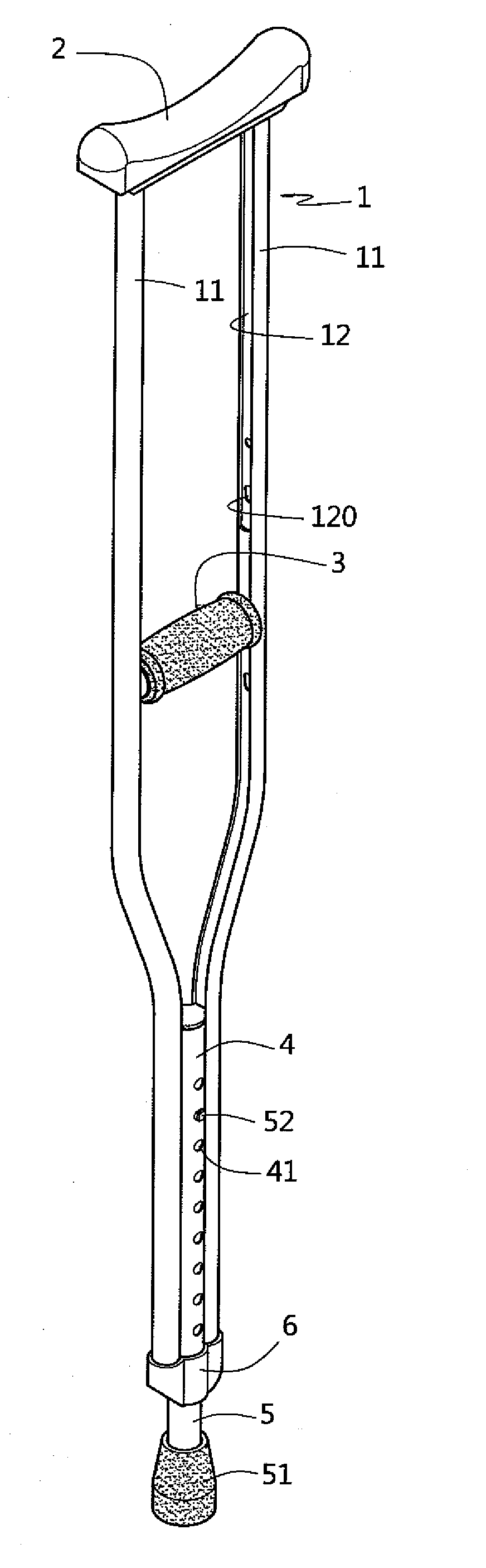
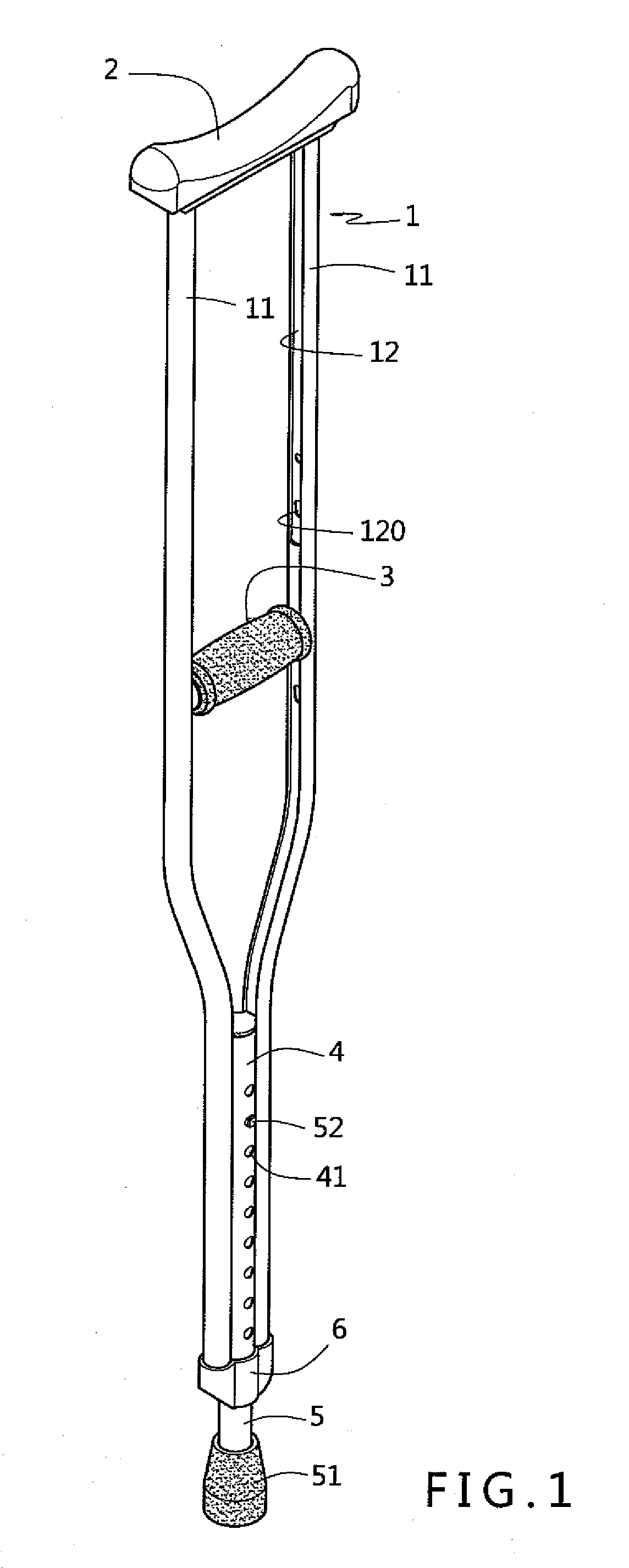
[0024]Referring to FIG. 1; the axillary crutch according to the invention includes a body 1 with a shoulder support 2 disposed on top of the body 1 for supporting users under the armpit; a lower tube 5 is disposed at a lower end of the body 1 that may be slid to adjust for positioning and leaning against the ground; a handgrip 3 is disposed in the middle of the body 1 for users to hold onto, wherein:

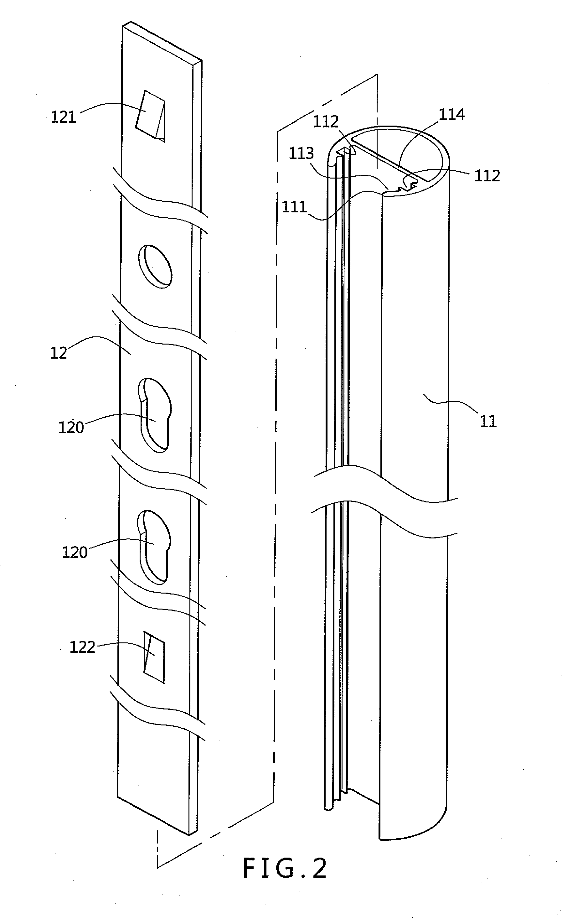
[0025]As shown in FIG. 2, the body 1 comprises two opposing shafts 11, and the two shafts 11 are disposed in parallel with an upper distance therebetween being wider and a lower distance therebetween being narrower; one side of each shaft 11 is formed with a slit 111 for receiving a handgrip 3, and two fastening grooves 112 are oppositely disposed on two lateral walls within the slit 111 of each shaft 11, respectively; a wall portion 12 made of a fortified material is disposed between the two fastening grooves 112, so that a sliding groove 113 that is wider interiorly and narrower exteri...


PUM


Abstract

An axillary crutch is disclosed in the invention; the axillary crutch has a body comprised of two opposite shafts, each shaft has a wall portion embedded therein, so that the wall portions may serve as the basis for adjusting and positioning a handgrip. Therefore, the shafts do not need to be formed with holes for securing the handgrip, which not only maintains the strength of the shafts, but also reinforces the strength and security of the axillary crutch as a whole because the shafts are embedded with fortified wall portions therein. Moreover, the position of the handgrip may be adjusted according to the length of a user's arm, and a pivot fitted into the handgrip may hold the opposite shafts together, which prevents the two shafts from becoming deformed or twisted, or buckling due to external forces.

Description

FIELD OF THE INVENTION[0001]The invention relates to an axillary crutch, and more particularly to a reinforced axillary crutch with adjustable handgrip.DESCRIPTION OF PRIOR ART[0002]In conventional axillary crutches as disclosed in U.S. Pat. No. 4,865,065, U.S. Pat. No. 4,852,597, RE32,815, U.S. Pat. No. 4,733,682, and U.S. Pat. No. 4,509,741; most are comprised of two parallel shafts with a wider upper distance therebetween and a narrower lower distance therebetween; a shoulder support for supporting users under the armpit is disposed on top of the pair of shafts; a handgrip is disposed between the shafts that may have its position adjusted, while a lower tube for positioning and supporting users is disposed at the lower end of the shafts. However, to allow the position of the handgrip to be adjusted according to the length of a user's arm, a plurality of openings are formed on the shafts for screw joints and butterfly nuts to fit into, but this also compromises the structural stre...

Claims


Application Information

Patent Timeline
Patent Type & Authority Applications(United States)
IPC IPC(8): A61H3/02
CPCA61H3/02
Inventor WENG, KUAN-JEN
Owner WENG KUAN JEN
Why Eureka
Try Eureka