Optical Potentiometer with Temperature Drift Compensation

a technology of temperature drift compensation and potentiometer, which is applied in the field of potentiometer, can solve the problems that the potentiometer type suffers from a number of problems, and achieve the effect of better control signal of the potentiometer

Inactive Publication Date: 2008-11-20
AIMBRIDGE
View PDF6 Cites 0 Cited by
  • Summary
  • Abstract
  • Description
  • Claims
  • Application Information

AI Technical Summary

Benefits of technology

[0029]Thus, according to this aspect of the invention, because groups of bars are provided with each group having bars of the same thickness, but the respective groups having bars of different thickness, a relatively long length of screen element can be provided within the confines of limitations provided by forming the bars on the screen element, to thereby provide greater sensitivity of the potentiometer. The greater sensitivity is achieved by enabling the length from a minimum thickness of the bars to a maximum thickness of the bars to be increased because of the plurality of bars in each group.
[0048]This aspect of the invention results in a more consistent change of the amount of light which passes through the screen element, thereby overcoming slight irregularities in the intensity detected by the light collector, and therefore providing a better control signal from the potentiometer.

Problems solved by technology

These types of potentiometers do suffer from a number of problems.

Method used


Image

  • Optical Potentiometer with Temperature Drift Compensation
  • Optical Potentiometer with Temperature Drift Compensation
  • Optical Potentiometer with Temperature Drift Compensation

Examples


Embodiment Construction

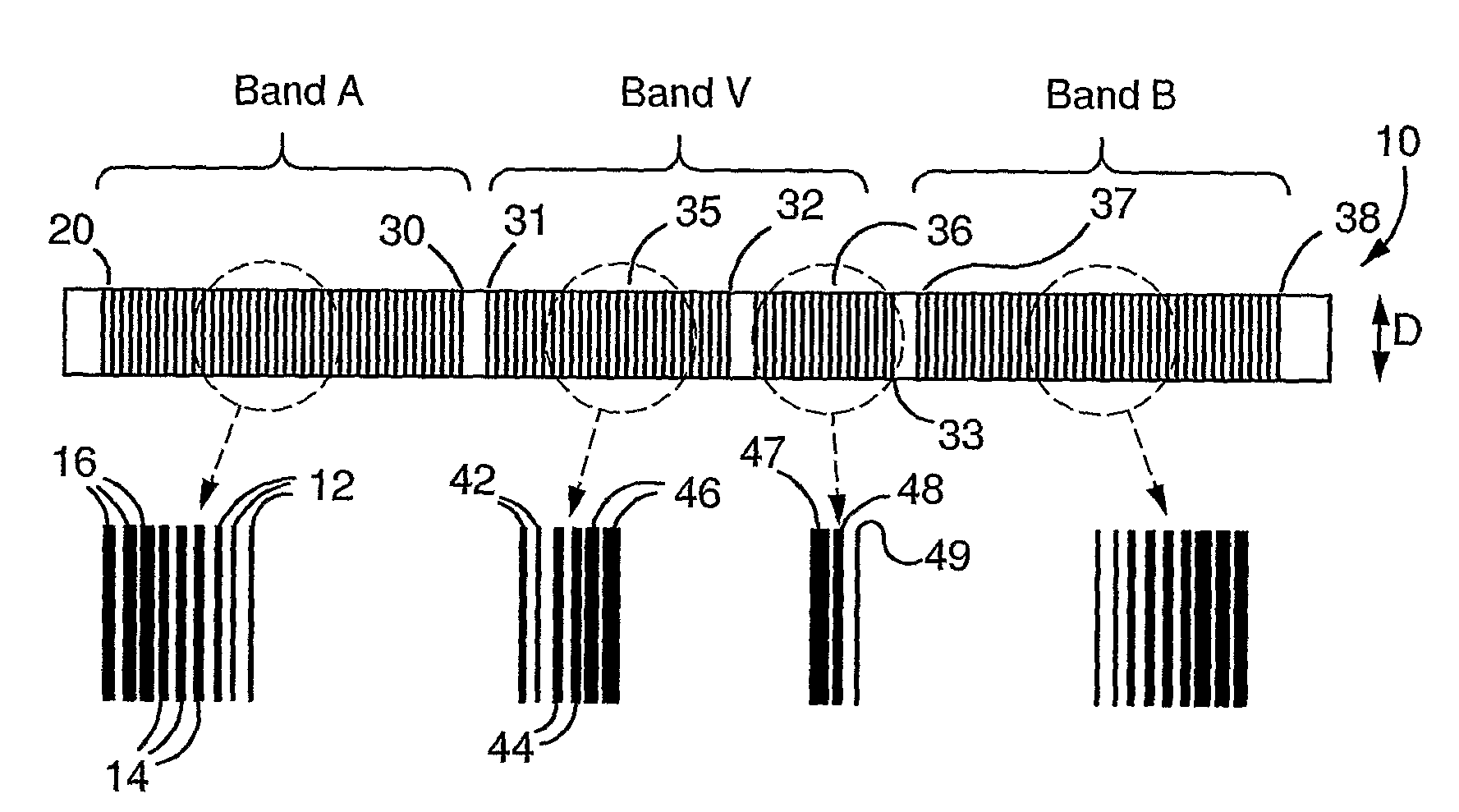
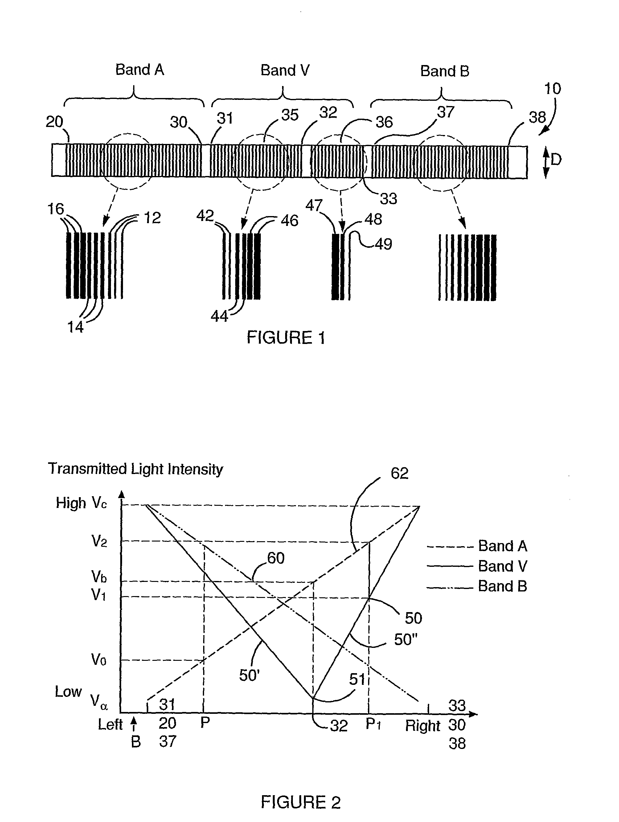
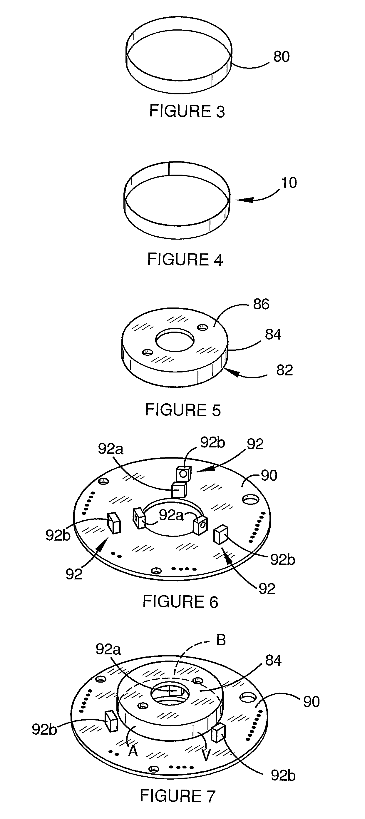
[0075]With reference to FIG. 1 a screen element 10 is shown which has a first section marked band A, a second section marked band V and a third section marked band B in FIG. 1. Each of the sections are provided with printed bars which are parallel with respect to one another and perpendicular to the direction of relative movement of the screen element 10 with respect to light emitters and collectors 92 which will be described with reference to FIGS. 6 and 7. Suffice it to say for the present purpose that in the preferred embodiment of the invention, one light emitter and one light collector is associated with each of the sections A, V and B as shown in FIG. 7. The parallel bars have centres which are spaced from one another by the same distance and are of different width to provide varying translucency because the space between edges of the bars will therefore decrease as the bars become thicker. Thus, the amount of light which is detected by the collector changes as the screen 10 m...


PUM


Abstract

A potentiometer is disclosed which comprises an opaque screen element (10) and light emitters and collectors (92) for transmitting light through the screen and detecting the light transmitted through the screen. The screen has three sections (A, V and B). The sections (A, V and B) have bars which are parallel to one another and extend transverse to the direction of movement of the screen (10). The section (A) has bars which are arranged in groups comprising the same number of bars, but each of a different thickness. The section (V) has two parts (35, 36), the first part has bars which are formed in the same manner as the section (A) except they are a mirror image to the bars in section (A) and each group comprises less bars than are in the groups in section (A). The second part of section (V) has individual bars which increase in thickness. Section (B) is a mirror image of section (A). This configuration allows for any drifting of voltage indicative of a change in light intensity which is detected by the emitter to be identified and compensated for because the intensity of light passing through the sections and plotted against position forms a U or V-shaped profile, with the apex identifying the maximum or minimum light intensity and therefore voltage at the collector.

Description

FIELD OF THE INVENTION[0001]This invention relates to a potentiometer and, in particular, but not exclusively, to a potentiometer for a control lever assembly for use in boats. The invention is an improvement to the potentiometer disclosed in our International Patent Application No. PCT / AU2005 / 001608 and corresponding Australian Provisional Patent Application Nos. 2004907143 and 2005904019. The contents of these applications are incorporated into this specification by this reference.BACKGROUND OF THE INVENTION[0002]As explained in the above International application, conventional potentiometers generally comprise variable resistors. These types of potentiometers do suffer from a number of problems. The invention in our above International application provides an optical potentiometer which addresses the disadvantages of potentiometers which comprise variable resistors.[0003]The potentiometer disclosed in our International application does operate extremely well but there is still ro...

Claims


Application Information

Patent Timeline
Patent Type & Authority Applications(United States)
IPC IPC(8): G01D5/26
CPCG01D5/34784
Inventor ROSENKRANZ, HANS-GUNTHERARMSTRONG, MARK FREDERICKRUSSELL, JAMESMAJOR, PETER JOHN
Owner AIMBRIDGE
Why Eureka
Try Eureka