Slip Control Boost Braking System

a technology of boosting braking and braking system, which is applied in the direction of braking system, braking components, transportation and packaging, etc., can solve the problem that the system is susceptible to no manual push through

Inactive Publication Date: 2008-11-20
KELSEY HAYES CO
View PDF40 Cites 57 Cited by
  • Summary
  • Abstract
  • Description
  • Claims
  • Application Information

AI Technical Summary

Benefits of technology

[0017]In yet another aspect of the present invention, a braking system includes a master cylinder bleed valve in fluid communication and disposed between a second intermediate chamber and a third intermediate chamber. The bleed valve controls a directional flow of brake fluid through the second intermediate chamber and the third intermediate chamber of the master cylinder during a no brake apply condition for purging entrapped gas from the master cylinder.

Problems solved by technology

Such systems are susceptible to having no manual push through if the isolation valves become inoperable in the closed position or if a hydraulic leak occurs.

Method used


Image

  • Slip Control Boost Braking System
  • Slip Control Boost Braking System
  • Slip Control Boost Braking System

Examples


Embodiment Construction

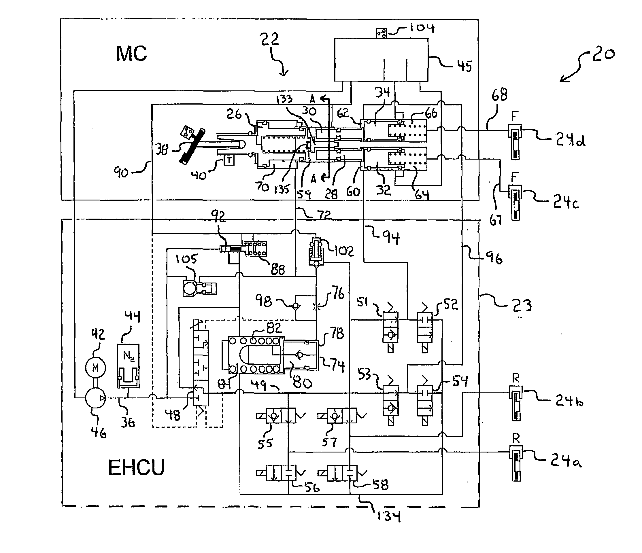
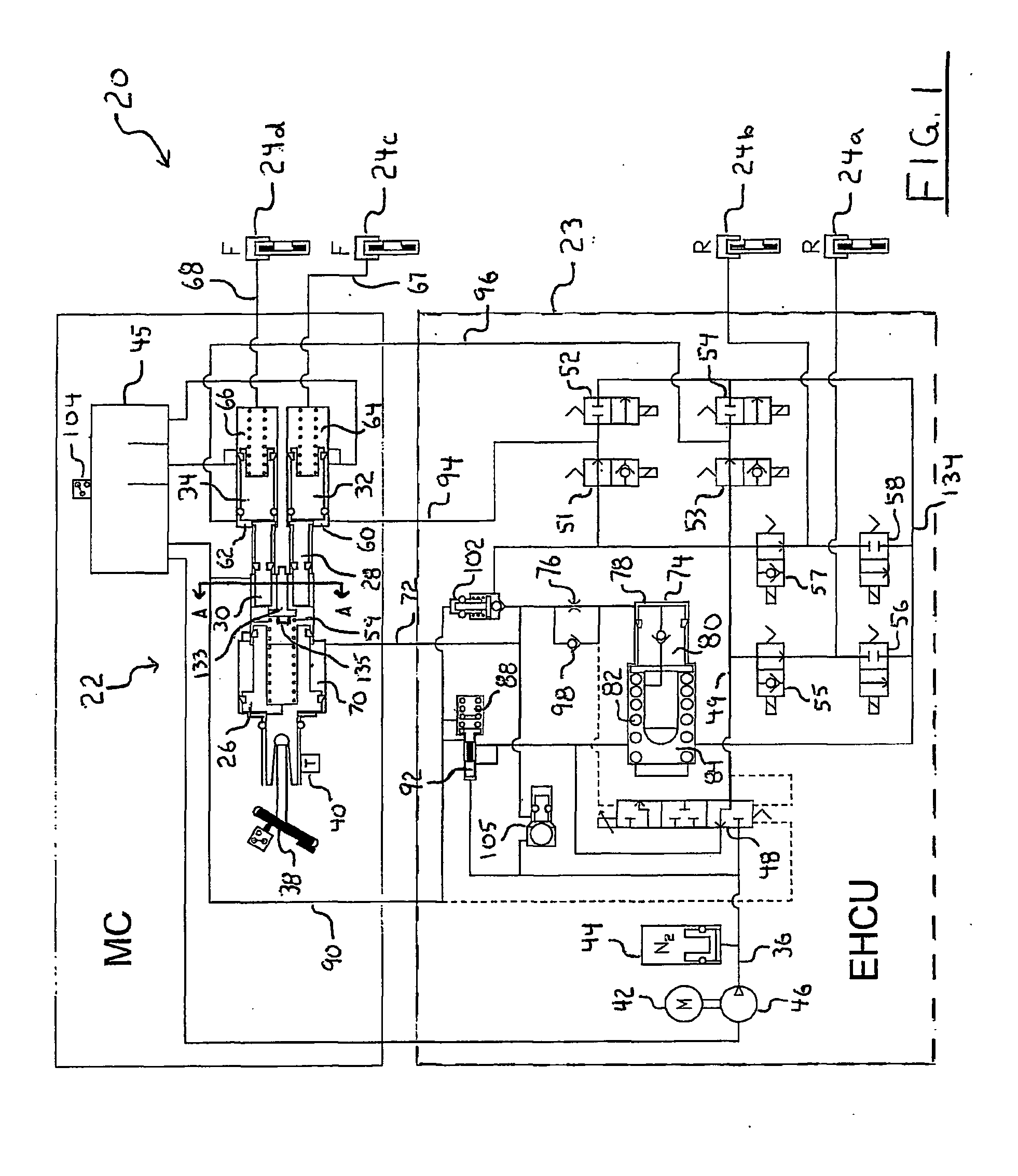
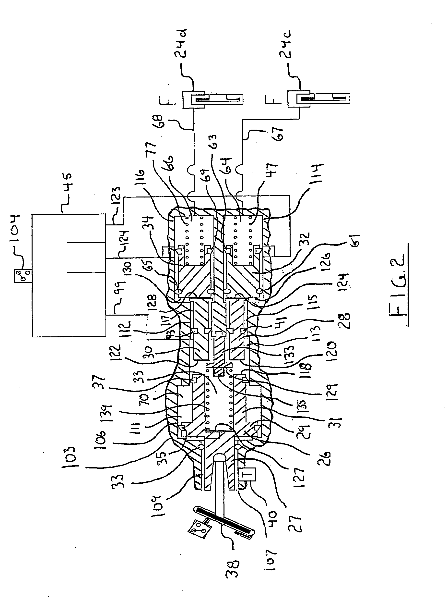
[0030]There is shown in FIG. 1, a first embodiment of a vehicle brake system indicated generally at 20, in accordance with the invention for applying active hydraulic boost in a braking system. The brake system 20 may suitably be used on a ground vehicle such as an automotive vehicle having four wheels and a brake for each wheel. Furthermore, the brake system 20 can be provided with other braking functions such as anti-lock braking and other slip control features to effectively brake the vehicle while simulating a normal response and pedal feel to the operator of the vehicle.

[0031]The brake system 20 includes a master cylinder 22 in fluid communication with a reservoir 45 that cooperatively acts with a brake module 23 for actuating a first vehicle brake 24a and a second vehicle brake 24b on a rear vehicle axle (not shown) and for actuating a third vehicle brake 24c and a fourth vehicle brake 24d of a front vehicle axle (not shown) for braking a vehicle. Each of the vehicle brakes 24...


PUM


Abstract

A braking system is provided for applying pressurized hydraulic brake fluid to a plurality of vehicle brakes. The system includes a source of pressurized brake fluid, a first brake fluid circuit, and a boost valve for controlling a flow of brake fluid from the source to the first circuit. A first brake actuator is actuated by brake fluid from the first circuit and a second brake actuator operated by an application of brake fluid from the first circuit. The system further includes a second brake fluid circuit and a third brake fluid circuit. A third brake actuator is actuated by brake fluid from the second circuit. A fourth brake actuator actuated by brake fluid from the third circuit. A master cylinder includes a primary piston, a first secondary piston, and second secondary piston. The first and second secondary pistons are capable of being each independently operably displaced by an application of pressurized fluid from the first circuit to pressurize brake fluid in, respectively, the second circuit to operate the third brake actuator and the third circuit to operate the fourth brake circuit.

Description

CROSS REFERENCE TO RELATED APPLICATIONS[0001]This application claims the benefit of U.S. Provisional Application No. 60 / 645,262 filed Jan. 20, 2005, U.S. Provisional Application No. 60 / 632,787 filed Dec. 3, 2004, U.S. Provisional Application No. 60 / 592,221 filed Jul. 29, 2004, and U.S. Provisional Application No. 60 / 568,748 filed May 6, 2004, the disclosures of which are hereby incorporated by reference.STATEMENT REGARDING FEDERALLY SPONSORED RESEARCH[0002]Not Applicable.BACKGROUND OF THE INVENTION[0003]1. Field of the Invention[0004]The present invention relates in general to a braking system for applying hydraulic braking control to vehicle brakes.[0005]More particularly, the present invention relates to a braking system for applying hydraulic braking during electrical and hydraulic failures.[0006]2. Description of the Related Art[0007]Electric-hydraulic braking systems typically include a manually powered master cylinder coupled to vehicle brakes on the vehicle wheels through iso...

Claims


Application Information

Patent Timeline
Patent Type & Authority Applications(United States)
IPC IPC(8): B60T8/44B60T7/12B60T7/20B60T8/34B60T8/40B60T13/14B60T17/18
CPCB60T7/12B60T8/34B60T8/4072B60T8/4077B60T13/142B60T17/18B60T7/20B60T8/44
Inventor GANZEL, BLAISE J.
Owner KELSEY HAYES CO
Why Eureka
Try Eureka