Voice coil motors and pre-compression generation devices thereof

a voice coil motor and pre-compression generation technology, applied in the direction of dynamo-electric components, dynamo-electric machines, instruments, etc., can solve the problems of inability to reduce the size and manufacturing costs of the motor, the structure of the driver is complicated, and the size of the motor cannot be reduced

Inactive Publication Date: 2008-11-20
IND TECH RES INST
View PDF14 Cites 27 Cited by
  • Summary
  • Abstract
  • Description
  • Claims
  • Application Information

AI Technical Summary

Benefits of technology

[0024]The position sensor comprises a Hall se

Problems solved by technology

Thus, the structure of the driver is complicated, and the size thereof cannot be reduced.
Nevertheless, as the lens driving device 1 must comprise a yoke 3 providing magnetic-permeable functions, the size and manufacturing costs thereof cannot be reduced.
The springs (resilient elements), however, are not easily manufactured and are easily deformed by external force, adversely affecting reduction of manufacturing costs of the lens driving devices.
Additionally, comprising springs (resilient elements), the size of the lens driving devices cannot be reduced.
However, reduction of the size of the voice coil motors is not easily achieved.
Moreover, although the permanent magnet radially magne

Method used


Image

  • Voice coil motors and pre-compression generation devices thereof
  • Voice coil motors and pre-compression generation devices thereof
  • Voice coil motors and pre-compression generation devices thereof

Examples


first embodiment

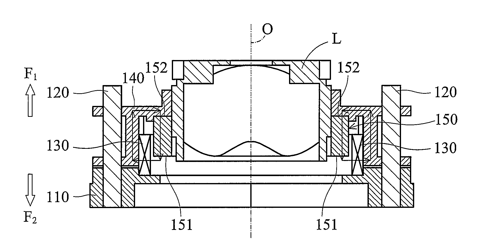
[0047]Referring to FIG. 2A and FIG. 2B, a voice coil motor 100 drives a lens module of a camera to perform zoom movement and comprises a fixed base 110, two opposite guide bars 120, a coil 130, a support base 140, and an annular magnetic member 150. The fixed base 110, guide bars 120, and coil 130 may be regarded as fixed members of the voice coil motor 100, while the support base 140 and annular magnetic member 150 may be regarded as movable members thereof.

[0048]The guide bars 120 are connected to the fixed base 110. Here, the guide bars 120 comprise magnetic-permeable material (or one of the guide bars 120 comprises magnetic-permeable material). Specifically, the guide bars 120 comprise a second central height plane H2, as shown in FIG. 2B.

[0049]The coil 130 is connected to the fixed base 110.

[0050]The support base 140 is movably fit on the guide bars 120. As shown in FIG. 2A, the support base 140 comprises a plurality of through holes 141 in which the guide bars 120 are fit. Nam...

second embodiment

[0056]Elements corresponding to those in the first embodiment share the same reference numerals.

[0057]Referring to FIG. 5, a voice coil motor 200 drives a lens module of a camera to perform zoom movement and comprises a fixed base 110, two opposite guide bars 120, a magnetic-permeable member 125, a coil 130, a support base 140, and an annular magnetic member 150. The fixed base 110, guide bars 120, magnetic-permeable member 125, and coil 130 may be regarded as fixed members of the voice coil motor 200, while the support base 140 and annular magnetic member 150 may be regarded as movable members thereof.

[0058]In this embodiment, generation of the first force F1 according to the Lorentz's law is the same as that of the first embodiment, and explanation thereof is omitted. The guide bars 120 comprise non-magnetic-permeable material and may be integrally formed with the fixed base 110 by injection molding. The magnetic-permeable member 125 comprises a third central height plane H3. In a...

third embodiment

[0061]Elements corresponding to those in the first embodiment share the same reference numerals.

[0062]Referring to FIG. 6A and FIG. 6B, a voice coil motor 100′ drives a lens module of a camera to perform zoom movement. Specifically, the voice coil motor 100′ comprises a position sensor 160 connected to the fixed base 110 and opposing the annular magnetic member 150. In this embodiment, the position sensor 160 may be a Hall sensor or a magnetic resistance sensing element.

[0063]Structure, disposition, and function of other elements in this embodiment are the same as those in the first embodiment, and explanation thereof is omitted for simplicity.

[0064]When the support base 140 and annular magnetic member 150 move along the magnetization direction of the annular magnetic member 150, the position sensor 160 detects the intensity of a magnetic field, in a fixed position in the voice coil motor 100′, provided by the annular magnetic member 150. Here, the intensity of the magnetic field in...


PUM


Abstract

A voice coil motor. At least one guide bar is connected to a fixed base. A coil is connected to the fixed base. A support base is movably fit on the guide bar. An annular magnetic member is connected to the support base and surrounded by the coil. A magnetization direction of the annular magnetic member parallels a moving direction of the support base and annular magnetic member. The annular magnetic member includes a first magnetic pole and a second magnetic pole. The first magnetic pole is disposed in the coil and separated from the bottom thereof. The second magnetic pole is disposed outside the coil. The coil interacts with the annular magnetic member to generate a first force, driving the support base and annular magnetic member to move along the magnetization direction of the annular magnetic member.

Description

BACKGROUND OF THE INVENTION[0001]1. Field of the Invention[0002]The invention relates to voice coil motors, and more particularly to voice coil motors with reduced size and manufacturing costs and enhanced positioning precision.[0003]2. Description of the Related Art[0004]Cameras disposed in cellular phones have been developed to provide high definition quality and reduced power consumption, manufacturing costs, and size. As such, actuators disposed in the cameras, for moving lens modules thereof, are critical.[0005]Automatic displacement driving devices applied in lens modules may employ drivers providing rotational power with a rotational axis thereof paralleling an optical axis of a lens module or drivers providing movement power with a moving direction thereof paralleling the optical axis of the lens module.[0006]An example of a driver providing rotational power with a rotational axis thereof paralleling an optical axis of a lens module is a stepping motor. The driver requires a...

Claims


Application Information

Patent Timeline
IPC IPC(8): G02B7/04H02K41/035
CPCG02B7/102H02K41/0356
Inventor LIU, CHIEN-SHENGLIN, PO-HENGWANG, YUNG-HSINGKE, SHUN-SHENGTSAI, MENG-CHECHANG, YU-HSIU
Owner IND TECH RES INST
Why Eureka
Try Eureka