[0006]The piston of the pump will slide in the cylinder from a first to a second position by supplying the pump inlet with a pressure medium. Valve members are received or incorporated in the piston itself and are actuated by the actuating members. By opening and closing the valve members at the appropriate times, the pressure medium that is brought into the cylinder during the movement of the piston from a first position to a second position will be transferred to the other side of the piston during the piston's return from the second position to the first position. In one embodiment, during the return
stroke to the first position, the first valve member is open and mutually connects the cylinder spaces on either side of the piston. During the movement of the piston from the first position to the second position, the pressure medium, which has been transferred from the pump inlet to the pressure chamber, is transported out of the pump via the pump outlet. During this piston
stroke the second valve member is in an open position connecting the pressure chamber to the outlet. A pressure medium moves the piston from the first position to the second position in the cylinder, and a resilient member will urge the piston from the second position to the first position. The interplay of the resilient member and piston enables the
piston pump to operate without requiring a separate motor for driving the pump. This results in a more efficient pumping and does not require separate drive means.
[0010]By moving the second
plunger from a first position to a second position an under-pressure will be created in the third chamber. This will cause uptake of a second medium from a third inlet. This will enable transport of this second medium from a tank (or the like) to an outlet. Preferably, the pump comprises second sealing means for sealing the third chamber against a return flow of medium. Further, the second pump preferably comprises a second connecting member connecting the second
plunger to the piston (and preferably also to the first
plunger) to simultaneously move the piston and second plunger (and preferably the first plunger) for transport of the pressure medium, and second medium (and preferably also the first medium) to the pump outlet. In a preferred embodiment, the pump outlet for the pressure medium, the first medium, and the second medium are the same. This results in a mixture of these media in the outlet flow. For example, in the case of the pressure medium being water and the first and second media being
soap concentrates, the outflow of the pump will be a
liquid soap ready for use. Preferably, the third inlet is at a different position as the second inlet to enable uptake of two different media, or the same medium at different altitudes in a tank with different densities. In case of the third inlet taking media from the same tank it is possible to have a mixture at the pump outlet of the pressure medium and two different densities of the other medium thereby creating a consistent mixture.
[0014]When the piston moves from the first position to the second position, and medium is transported from the pressure chamber to the pump outlet, part of the outgoing medium is temporarily stored by the absorber. This stored volume is output during the return movement of the piston from the second position to the first position due to the
compressed air volume on the other side of the plunger. This smoothens the pump output.
[0016]The disposing means will provide a certain amount of one or more agents into one of the chambers of the
piston pump during a
stroke of the piston and / or plungers. Such agent may include a colouring agent supplying a specific colour to the inlet space of the pressure medium, thereby colouring the outflow from the
piston pump. This will be relevant e.g. in case the outflow of the piston pump has the same colour as the incoming flow. E.g. in case of the pressure medium being water and the first and / or second medium being a
soap concentrate a colouring agent will enable to distinguish the ingoing water from the outgoing
soap. Also other agents may be used to provide specific characteristics to the outflow of the piston pump. Preferably, the pump comprises connecting means for connecting the tank of agents medium to the pump. This enables the provision of a single piece of equipment for both the pump and the agent disposal means. Furthermore, by directly
coupling the agent medium to the pump it is possible to use the movement of the piston for disposal of the agent in the main pressure chamber related to this piston.
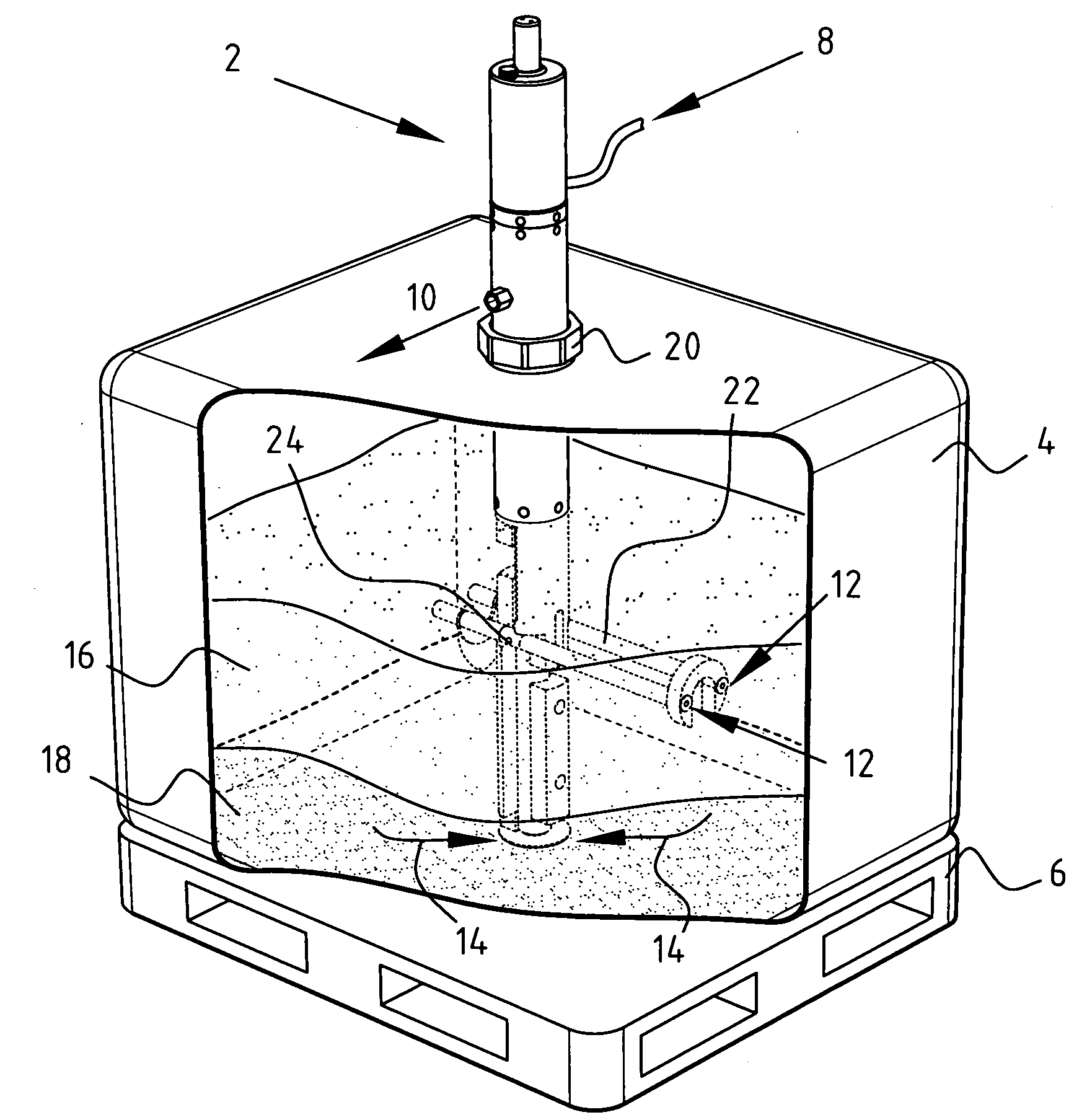
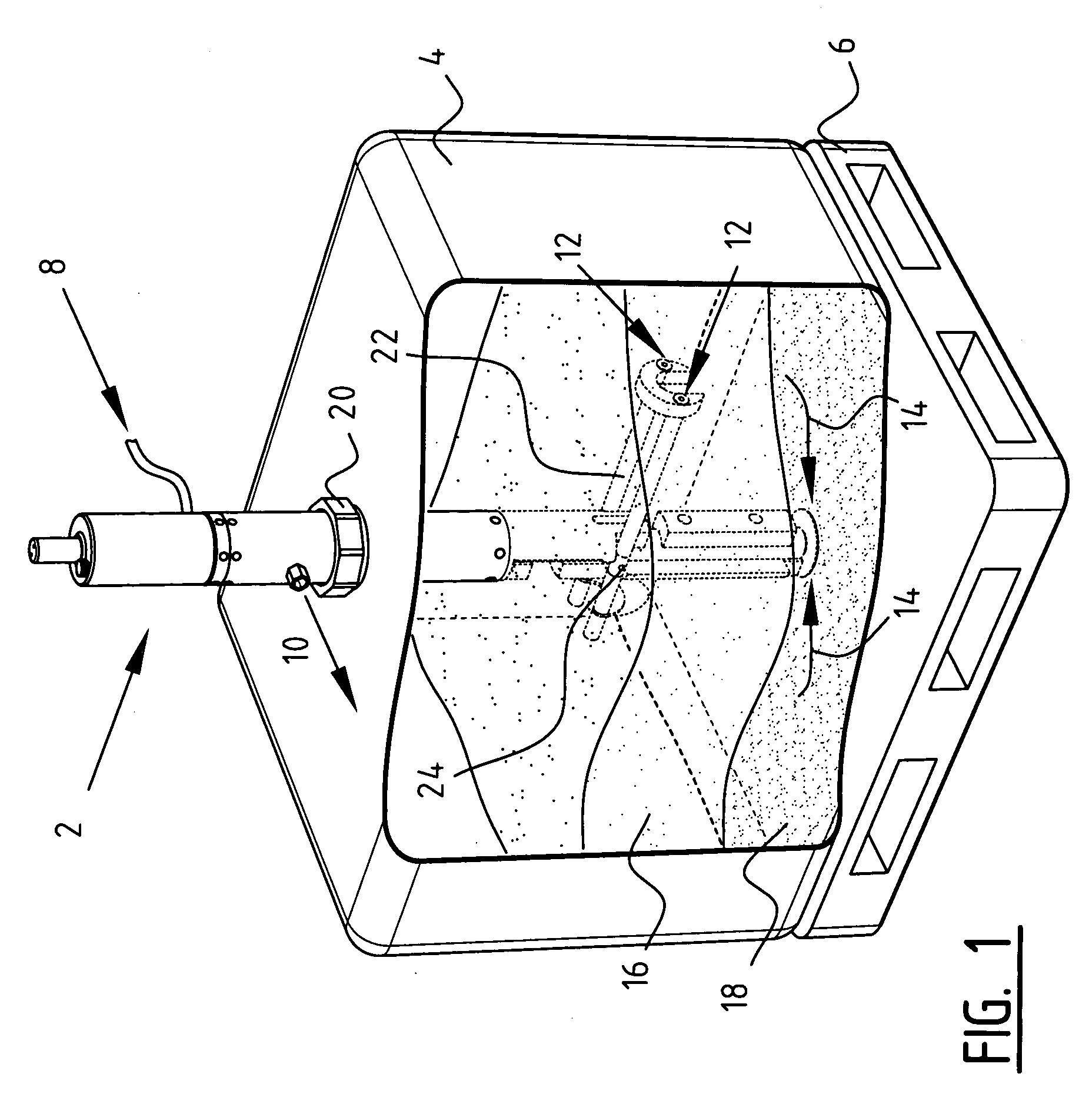
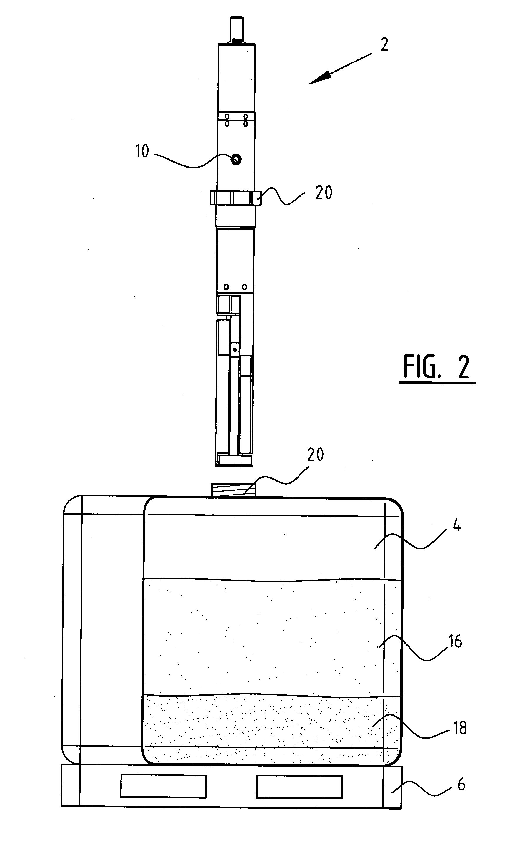
[0018]A fluid, like water, used for the pressure medium would allow for movement of the piston in the cylinder. Furthermore, as the piston is moved due to the resilient means, the fluid is transported to the pump outlet and preferably mixed with one or two other media like, for example, soap concentrate. Such soap concentrate may constitute of a mix of various chemicals with a rather large variation of molecular weight. This concentrate may be taken from a
storage tank. Typically, after a relatively short period of time, such as about 5 minutes, it is possible to distinguish an upper part of, for example, 60%
low density concentrate and a lower part of, for example, 40% higher density concentrate. To achieve a consistent outflow of soap at the pump outlet such a mixture must reflect the differences in density of the soap concentrate. In the example mentioned here, 60% of the soap concentrate has to be taken from the upper part by the third inlet of the pump and the remaining 40% of the lower part by the second inlet of the pump. Depending on the desired characteristics of the
soap product, the ratio of soap to water will vary. Different ratios may be achieved by changing the dimensions of the pump parts. For example, different uptakes of volume from the
storage tank by the second and / or third inlet will be possible. By choosing the second and third chambers of the desired dimensions it is possible to have an outflow with every desired concentrations of media. Although in the preferred embodiment the ratio of the first pressure chamber and second chamber is about 1:11, also ratios 1:10 and 1:12 are possible. However, it will be understood that far different ratios will be possible, such as anywhere between 1:1 and 1:100, depending on the density differences in the relevant media. This will include the ratios 1:23 and 1:35 that are also relevant for soap concentrates.


