Stents for angioplasty

Inactive Publication Date: 2008-11-20
SORIN BIOMEDICA CARDIO SRL
View PDF48 Cites 59 Cited by
  • Summary
  • Abstract
  • Description
  • Claims
  • Application Information

AI Technical Summary

Benefits of technology

[0017]In a second aspect, this invention is a method of preventing restenosis

Problems solved by technology

These stresses often cause the stent to perform in an undesirable manner.
Additionally, a significant disadvantage of current stent designs is their failure to distribute these stresses throughout the structure of the stent.
This results in at least two problems.
First, an overlap of the ma

Method used


Image

  • Stents for angioplasty
  • Stents for angioplasty
  • Stents for angioplasty

Examples


Example

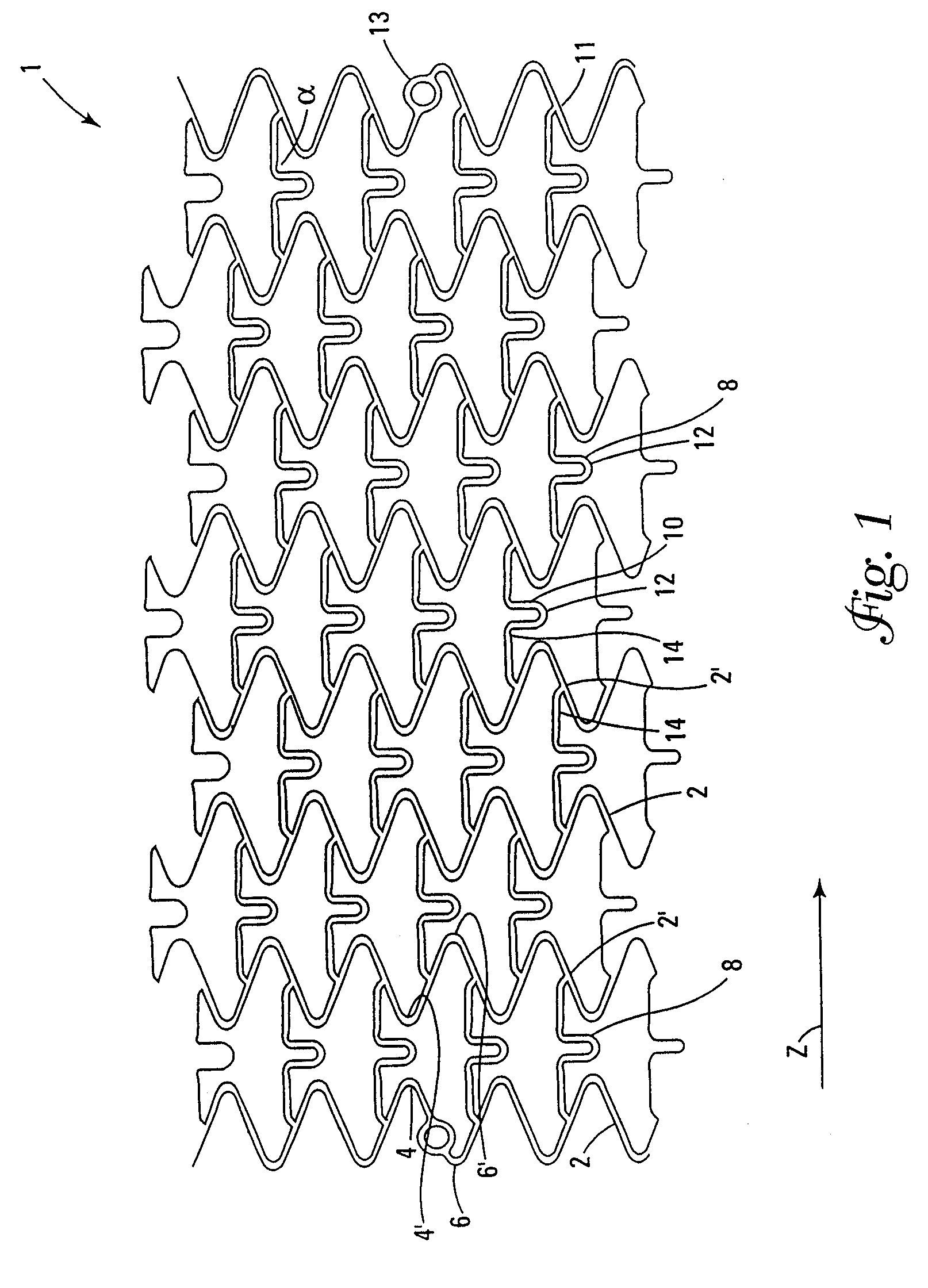
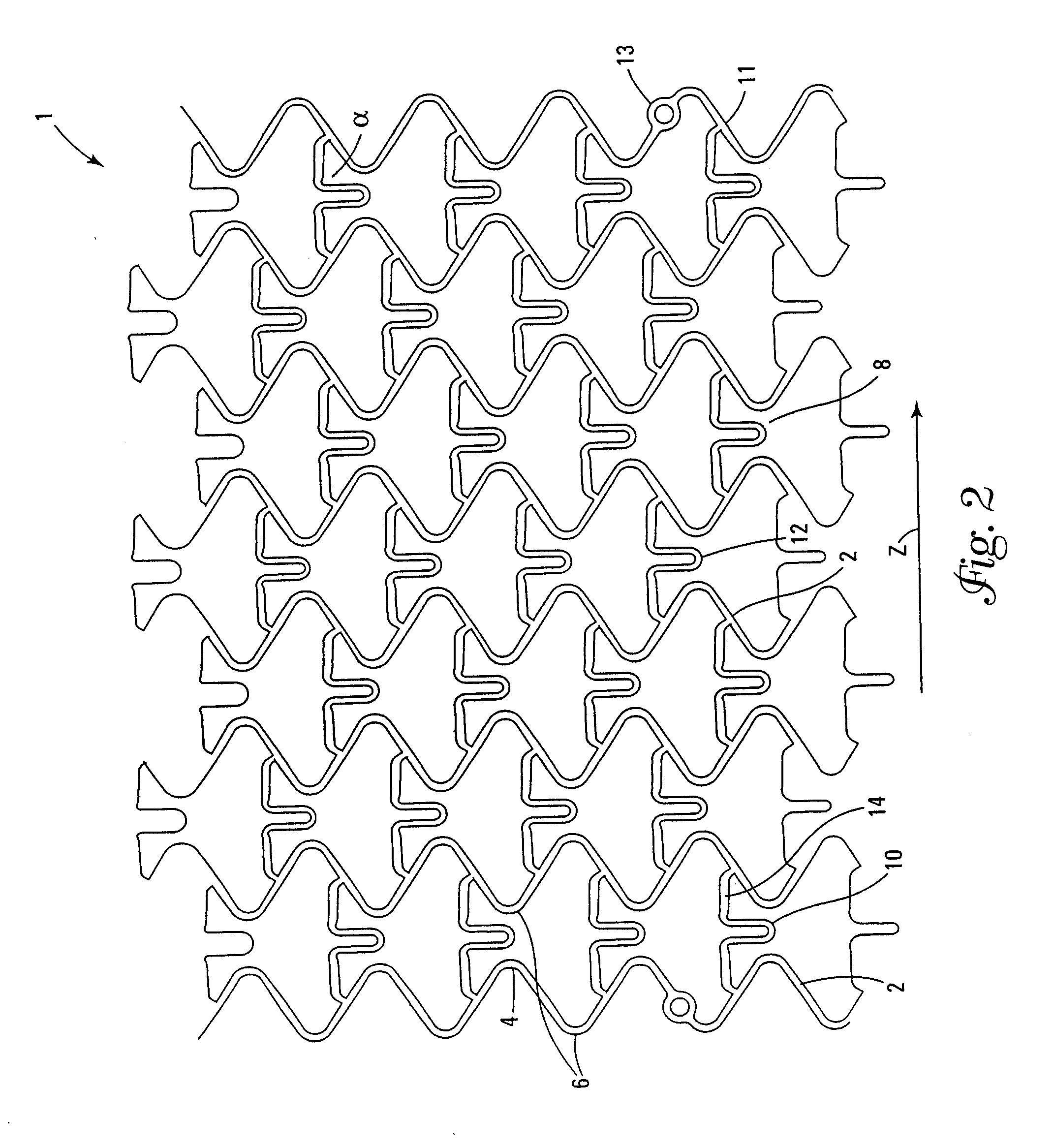
[0032]A stent is inserted into a lumen, such as a blood vessel, at a site where stenosis, i.e., narrowing or stricture, is to be corrected. The stent is a tubular envelope, tubular body, or cylinder having apertured walls, such as, for example, a mesh-like structure. The stent typically has dimensions between several millimeters and several tens of millimeters in length, and a wall thickness of the order of, for example, several hundredths of millimeters. The stent is normally positioned in situ by catheterisation through the vasculature followed by radial expansion from an introduction diameter of, for example, about 1.0 to 1.5 mm, to an expanded diameter of, for example, about 3 to 4 mm. In this expanded condition, the stent exerts a supporting force on the lumen, thereby avoiding or at least slowing restenosis of the vessel. In general, the external diameter of the stent in the radially-contracted condition is chosen to enable the introduction of the stent into a lumen, while the...


PUM


Abstract

This invention is a stent having a substantially tubular body defining a longitudinal axis comprising first and second adjacent annular segments, each segment defining a substantially sinusoidal shape having a plurality of peaks and valleys, the peaks of the first segment extending toward the second segment and being aligned longitudinally with the valleys of the second segment. The stent has a plurality of bridge elements having a U-shaped portion between first and second connector arms, the first connector arm of one bridge element being connected between a first peak and a first valley of the first segment and the second connector arm being connected between a first peak and a first valley of the second segment.

Description

[0001]This application is a continuation of patent application Ser. No. 10 / 159,969, filed May 31, 2002, now U.S. Pat. No. 7,273,494 B2, which is a continuation of patent application Ser. No. 09 / 410,303, filed Oct. 1, 1999, now U.S. Pat. No. 6,451,049 B2, which is a continuation-in-part of patent application Ser. No. 09 / 069,425, filed Apr. 29, 1998, now U.S. Pat. No. 6,325,821 B1, the contents of each of which are hereby incorporated by reference herein.FIELD OF THE INVENTION[0002]The present invention relates to stents for angioplasty. In particular, the invention relates to a stent having a cellular design.BACKGROUND OF THE INVENTION[0003]The term “stent” is intended to indicate devices useful for endoluminal insertion (for example, in a blood vessel), usually effected by means of catheterisation, with subsequent deployment in place so as to achieve local support of the lumen. The primary purpose of the stent is to eliminate and avoid the restenosis (i.e., narrowing or closure) of ...

Claims


Application Information

Patent Timeline
IPC IPC(8): A61F2/82A61F2/84A61F2/91A61F2/915
CPCA61F2/91A61F2/915A61F2230/0013A61F2002/91583A61F2002/91541
Inventor ROLANDO, GIOVANNIGASCHINO, PAOLO
Owner SORIN BIOMEDICA CARDIO SRL
Why Eureka
Try Eureka