Oxygen sensor socket removal and installation tool

a technology for installing tools and oxygen sensors, which is applied in the field of tools, can solve the problems of difficult and/or tedious removal and replacement of oxygen sensors in exhaust systems, not always adequately useful, and corroded oxygen sensors, etc., and achieves the effect of convenient us

Inactive Publication Date: 2008-11-27
LISLE CORPORATION
View PDF7 Cites 8 Cited by
  • Summary
  • Abstract
  • Description
  • Claims
  • Application Information

AI Technical Summary

Benefits of technology

[0007]A further object of the invention is to provide a tool which permits ease of removal of an oxygen sensor wherein the too

Problems solved by technology

However, oxygen sensors have a tendency to become corroded and thus removal and replacement thereof in an exhaust system is often a difficult and/or a tedious undertaking.
While such prior tools are helpful and utilitarian, t

Method used


Image

  • Oxygen sensor socket removal and installation tool
  • Oxygen sensor socket removal and installation tool
  • Oxygen sensor socket removal and installation tool

Examples


Embodiment Construction

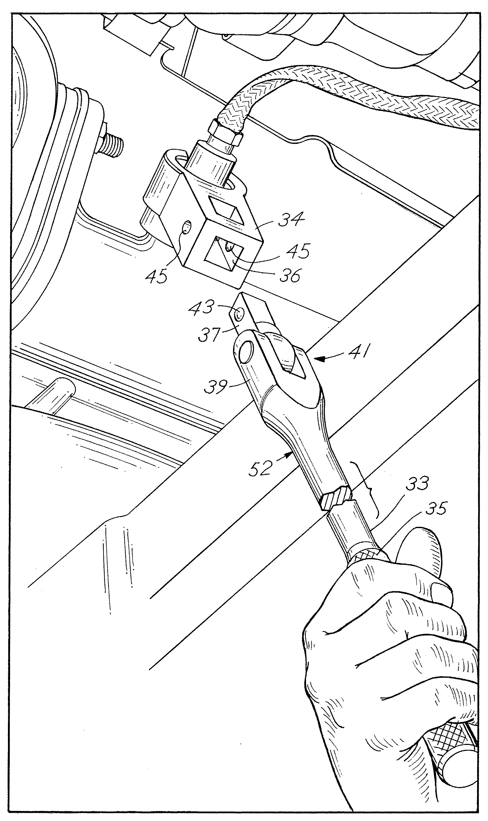
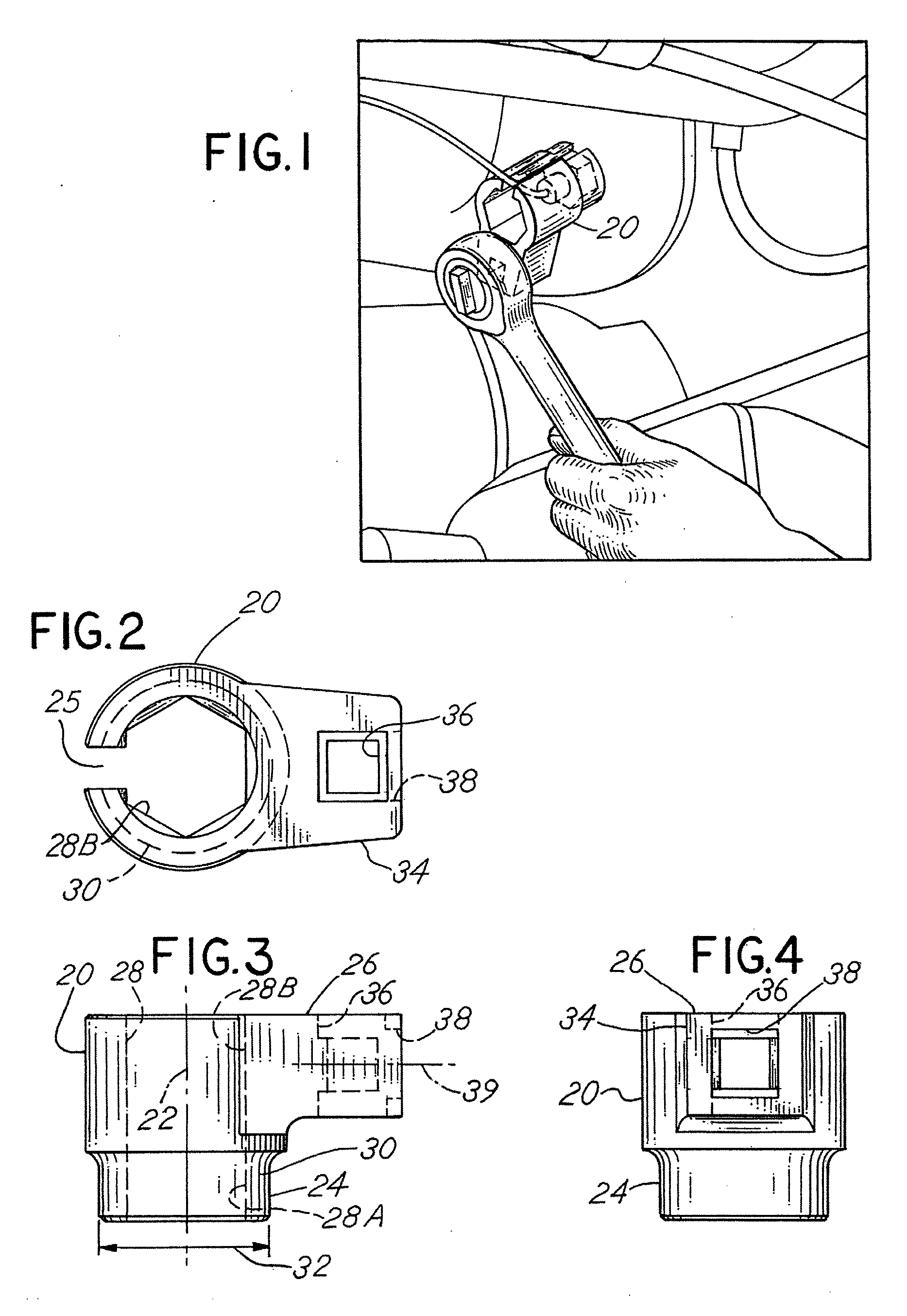
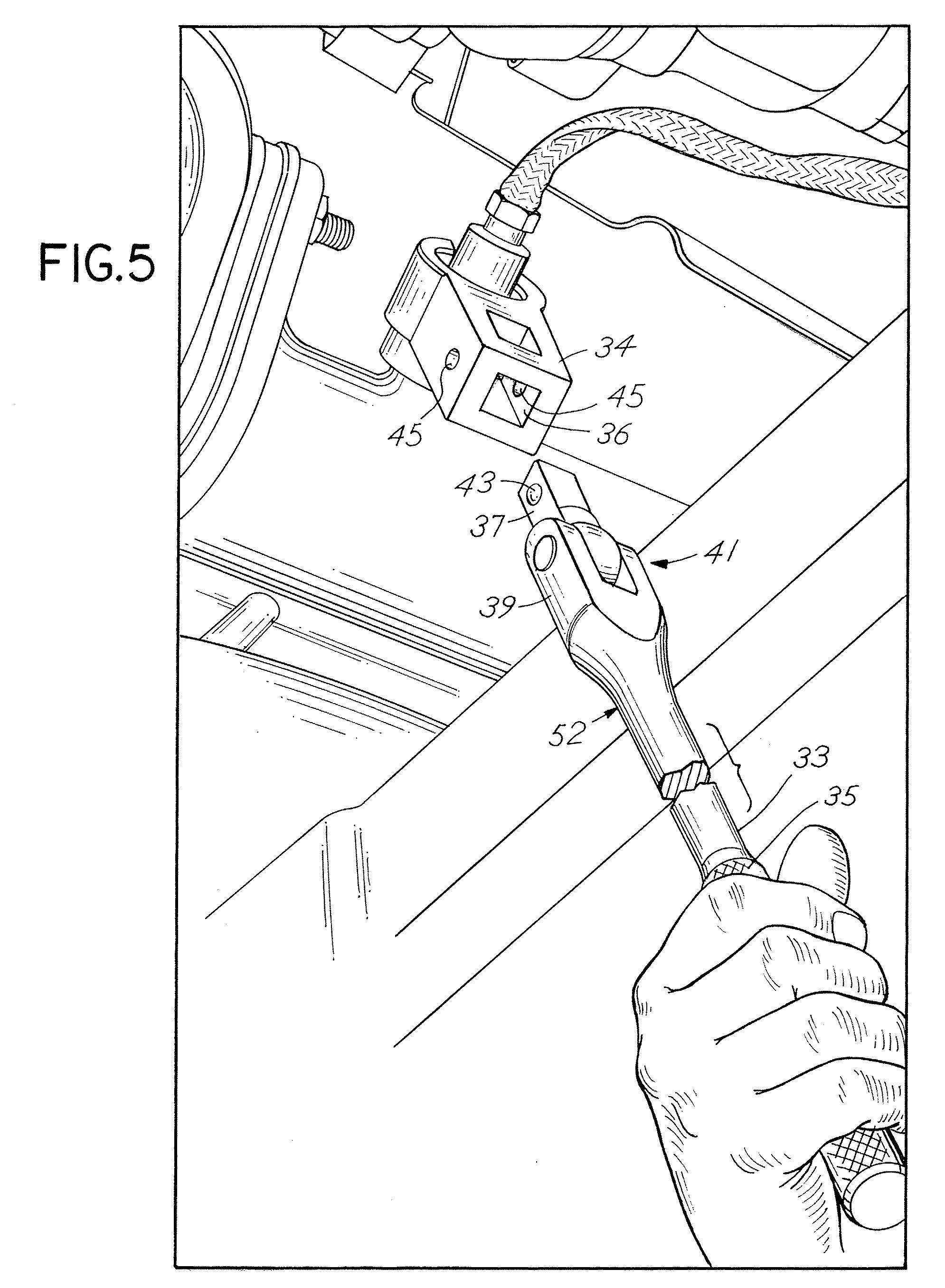
[0015]Referring to the figures, the tool for removal of an oxygen sensor from a vehicle exhaust system comprises a socket body 20 which includes a longitudinal centerline axis 22. The socket body 20 further includes an oxygen sensor engaging end or section 24 and a socket drive receiving end 26 located respectively coaxially at opposite ends of the body 20. The body 20 thus includes a throughbore 28 which is configured at the oxygen sensor engaging end 24 with an internal polygonal cross sectional bore configuration compatible with the outside configuration of an oxygen sensor. A longitudinal slot 25 in body 20 is provided for oxygen sensor lead wires. The oxygen sensor engagement end 24 further includes a generally circular outside peripheral surface 30 which has a diameter 32 in the range of 1.250±0.25 inches. Preferably, the nominal dimension of that surface 30 is 1.250 inches. This enables the removal tool to be utilized for the effective removal and / or replacement of oxygen sen...


PUM


Abstract

An oxygen sensor removal tool includes an axial throughbore with an oxygen sensor socket bore at one end and a socket drive bore at the opposite end, and further including a radially extending drive socket arm with a drive socket opening so that the tool may be placed over an oxygen sensor and a socket drive or other drive may be attached to the tool to provide for effective force to permit adequate torque to disengage the oxygen sensor from a vehicle exhaust system.

Description

CROSS REFERENCE TO RELATED APPLICATION[0001]This is a continuation-in-part application of Ser. No. 11 / 751,865 filed May 22, 2007 entitle “Oxygen Sensor Socket Removal and Installation Tool” which is incorporated herewith by reference and for which priority is claimed.BACKGROUND OF THE INVENTION[0002]In a principal aspect the present invention relates to a tool which may be used to remove and / or install an oxygen sensor typically mounted in a motor vehicle exhaust system. The tool is thus capable of utilization for the removal or replacement of an oxygen sensor located in restricted access location.[0003]Modern motor vehicles include internal combustion engines which feature the utilization of an oxygen sensor. Data from the oxygen sensor is utilized by an onboard computer to effect more efficient internal combustion by the engine. Often it is necessary to replace the oxygen sensor. However, oxygen sensors have a tendency to become corroded and thus removal and replacement thereof in...

Claims


Application Information

Patent Timeline
IPC IPC(8): B25B13/06B25B13/50
CPCB25B13/06B25B13/481
Inventor WHITEHEAD, MICHAEL L.GOODRICH, MICHAEL J.
Owner LISLE CORPORATION
Why Eureka
Try Eureka