Method and Apparatus for a Gauge for Indicating a Pressure of a Fluid

a technology of fluid pressure and gauge, applied in the direction of fluid pressure measurement, pressure difference measurement between multiple valves, instruments, etc., can solve the problems of exacerbated problems and inaccurate measurement, and achieve the effect of reducing calibration tim

Inactive Publication Date: 2008-11-27
GORDON JOSEPH B
View PDF13 Cites 10 Cited by
  • Summary
  • Abstract
  • Description
  • Claims
  • Application Information

AI Technical Summary

Benefits of technology

[0009]Another object is a gauge that is

Problems solved by technology

If the lag is not accounted, the measurement may not be accurate.
This problem can be exacerbated if calibration needs to be perf

Method used


Image

  • Method and Apparatus for a Gauge for Indicating a Pressure of a Fluid
  • Method and Apparatus for a Gauge for Indicating a Pressure of a Fluid
  • Method and Apparatus for a Gauge for Indicating a Pressure of a Fluid

Examples


Embodiment Construction

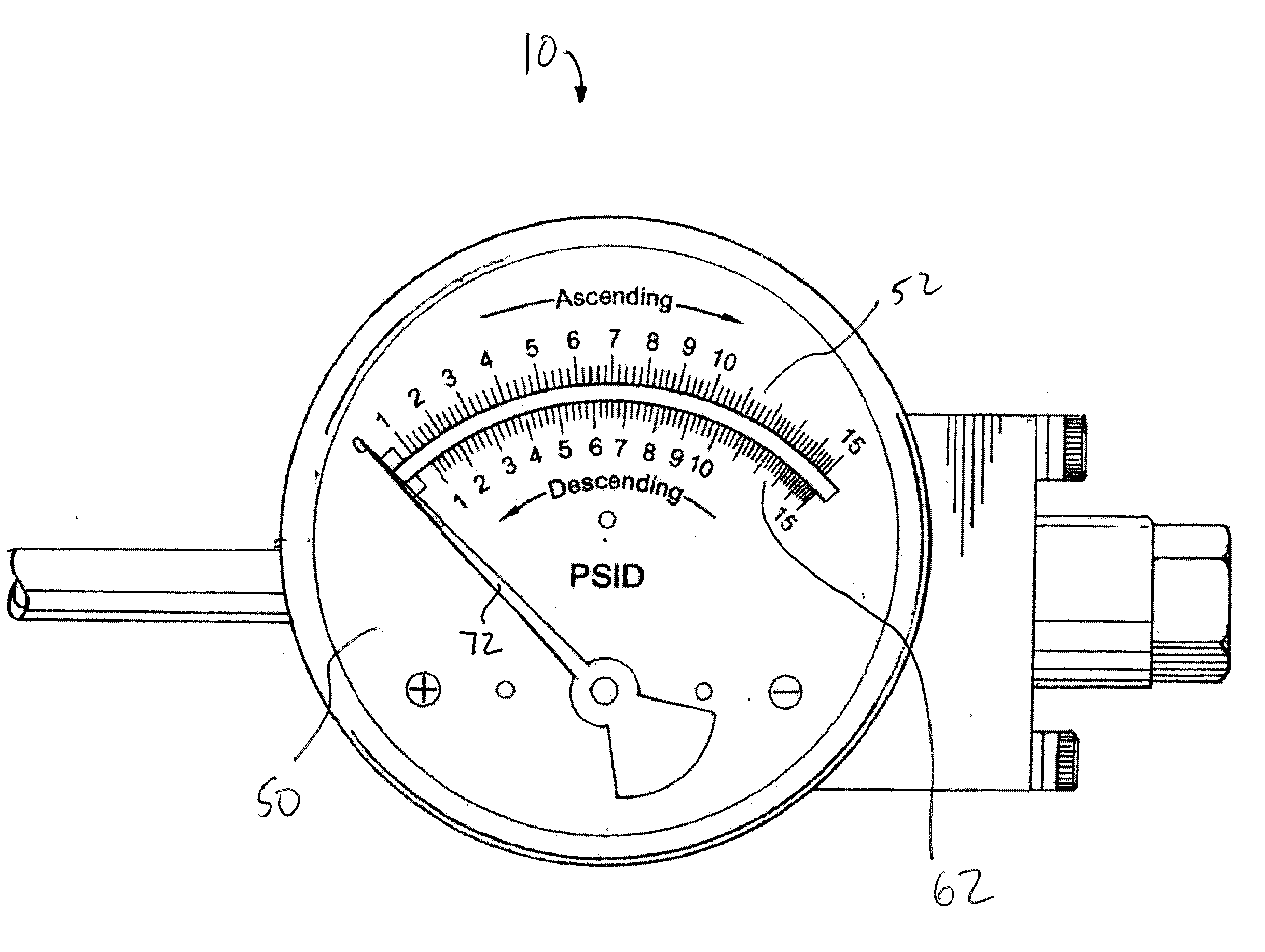
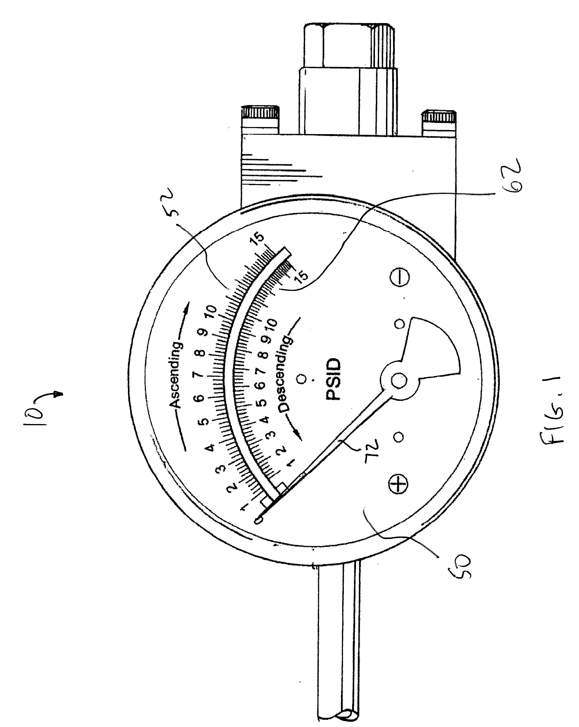
[0029]FIGS. 1 and 3a-3d depict gauge 10 in accordance with the invention. As shown, gauge 10 includes face 50, first inlet 20, and second inlet 30. Face 50 indicates a pressure difference between first inlet 20 and second inlet 30 and for calibration purposes, includes first 52 plurality of graduation marks and second 62 plurality of graduation marks for calibrating gauge 10 as the pressure is ascending or descending, respectively.

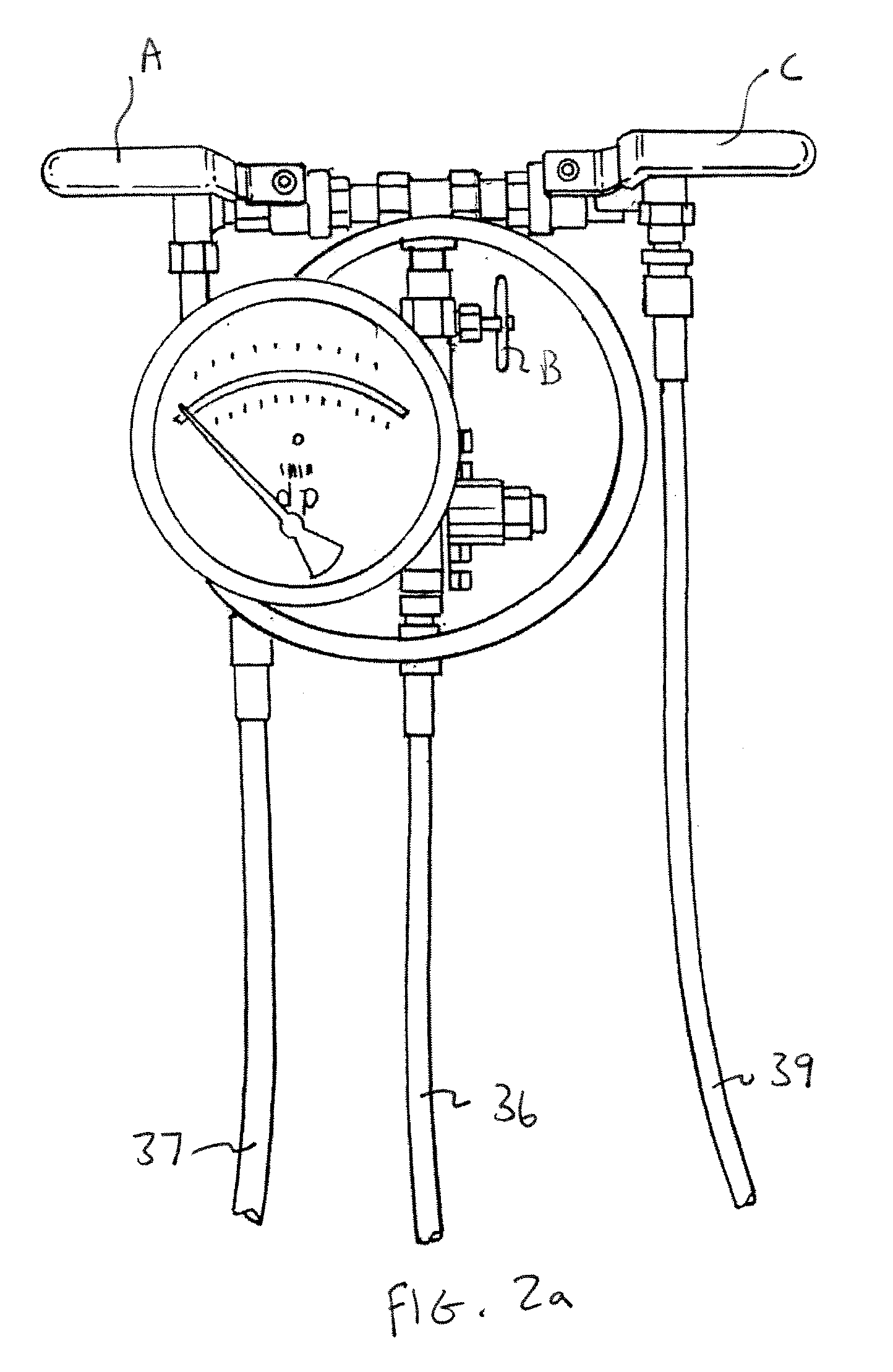
[0030]As shown, each 54 mark of first 52 plurality of graduation marks indicates a pressure in an ascending direction. Each 64 mark of second 62 plurality of graduation marks indicates a pressure in a descending direction. Referring to FIG. 2, to determine a pressure differential across an article, such as a filter, first hose 36 (which is usually attached to one side of the article) is attached to first inlet 20 and second hose 37 (which is usually attached to the opposite side of the article) is attached to second inlet 30. A pressure differential, or lo...


PUM


Abstract

The invention relates to a method and apparatus for a gauge for indicating a pressure of a fluid, including a gauge having a face where the face has a first plurality of graduation marks, each for indicating a pressure in an ascending direction. The face also has a second plurality of graduation marks, each for indicating a pressure in a descending direction. In addition, the gauge includes a sensor magnet for detecting the pressure of the fluid, a pointer magnet coupled to a pointer and in communication with the sensor magnet for moving the pointer in correspondence with a movement of the sensor magnet, and wherein the pointer traverses across both the first and second pluralities of graduation marks for indicating the pressure of the fluid in either an ascending direction or descending direction.

Description

FIELD OF THE INVENTION[0001]The invention relates to a pressure gauge for measuring a difference in pressure in either an ascending or descending direction.BACKGROUND OF THE INVENTION[0002]Differential pressure gauges are typically known in the art for aiding in monitoring the volumes of gases or liquids. A differential pressure gauge often functions by monitoring pressure on opposite sides of a piston-magnet or diaphragm-magnet sensor. Changes in the pressure difference will normally cause the sensor assembly to move in proportion to the change.[0003]A rotary magnet, usually located in a separate body cavity and isolated from acting pressures, is typically rotated by magnetic coupling to linear movement of the sensor magnet. A pointer attached to the rotary magnet may indicate differential pressure on an easy to read dial.[0004]However, there is usually a lag in position and / or time between the movement of the sensor magnet and the rotary magnet because the rotary magnet follows th...

Claims


Application Information

Patent Timeline
IPC IPC(8): G01L13/02G01L19/16
CPCG01L7/104
Inventor GORDON, JOSEPH B.
Owner GORDON JOSEPH B
Why Eureka
Try Eureka