Spring biased slide arrangement for anti-bow roller tube

a technology of anti-bow and roller tubes, which is applied in the direction of door/window protective devices, instruments, shutters/movable grilles, etc., can solve the problems of downward “sagging” deflection in the central portion of the roller tube with respect to the supported end, sagging deflection in the conventionally supported roller tube can also have a detrimental effect on operation, etc., to achieve the effect of reducing the force of the roller tub

Active Publication Date: 2008-11-27
LUKOS STEPHEN
View PDF42 Cites 38 Cited by
  • Summary
  • Abstract
  • Description
  • Claims
  • Application Information

AI Technical Summary

Benefits of technology

[0013]The apparatus can further comprise a first spring coupled to the first slide member for applying a first force to the first end of the roller tube in an upward direction when the roller tube is positioned in the housing to dispense material therefrom in a downward direction. Typically, the first spring is provided at the end of the roller tube that contains a motor. In such an embodiment, the first spring compensates, at least in part, for the weight of the motor. A second spring may be coupled to the second slide member for applying a second force to the second end of the roller tube in an upward direction when the roller tube is positioned in the housing to dispense material therefrom in a downward direction. The second spring may not be necessary, as the first spring alone may be adequate to enable the material to wind up on the roller tube evenly. In the event a second spring is required, it is often possible to use a lighter spring than the first spring, particularly when the first spring is offsetting the weight of the motor and the second spring is not. One reason to provide a second spring at the idler end of the roller tube would be to reduce the force of the roller tube against the support cradle in order to prevent the free cut end of the material on the roller tube from stretching, curling or getting wavy due to the pressure of the material against the support cradle. This same consideration also applies to the motor side of the roller tube, and the spring(s) on that side serve a similar function to prevent unwanted deviations at the edge of the cut fabric.

Problems solved by technology

The response of a roller tube, supported at its ends in a conventional manner, from the weight of a flexible sheet material as well as from self-weight of the tube, results in a downward “sagging” deflection in a central portion of the roller tube with respect to the supported ends.
For roller tubes used with wider sheet materials (e.g., widths of 10 to 30 feet or more), support of the correspondingly long roller tubes in a conventional manner can result in sagging deflection detrimental to the appearance of a supported sheet material.
Sagging deflection in a conventionally supported roller tube can also have a detrimental effect on operation.
Moreover, any deflection in the roller tube can cause permanent damage to the sheet material (e.g. fabric, vinyl, polyester, acrylic, fiberglass).
Video projection screen material is particularly prone to damage reducing visibility and performance over time.
Such uneven tracking can cause the opposite end portions of the sheet material to be wound more tightly onto the end portions of the roller tube than the central portion of the roller tube.
As a result, the central portion of the sheet material is not pulled tightly to the tube causing it to tend to buckle.
This buckling of the central portion of the sheet material, if severe enough, can create variations in radial dimensions of the rolled sheet material along the length of the tube, thereby impairing subsequent rolling of lower portions of the sheet material.
Uneven tracking can also cause surface discontinuities, known as “golf balling,” that include a permanent sagging pocket shaped discontinuity in the sheet material.
After each revolution of the roller tube, as the material winds up on the tube, the imperfections (e.g., wrinkles) in the material, and particularly in the center thereof, will worsen.
Although increasing the roller tube diameter serves to reduce sagging deflection in conventional end-supported tubes, there are undesirable consequences associated with such a solution.
Increasing the diameter of the roller tube increases weight, thereby potentially affecting the size and type of structure capable of providing rotatable support for the tube.
Also, additional space required by the larger diameter roller tube and its associated support structure may not be readily available in many installations.
Even if space is available, the bulky nature of the system due to the required large roller tube diameter is often objectionable for aesthetic reasons.
The elongate support rollers add weight and complexity to the roller tube system.
The increased costs and failure mechanisms inherent in the more complex support systems diminish the advantages provided.

Method used


Image

  • Spring biased slide arrangement for anti-bow roller tube
  • Spring biased slide arrangement for anti-bow roller tube
  • Spring biased slide arrangement for anti-bow roller tube

Examples


Embodiment Construction

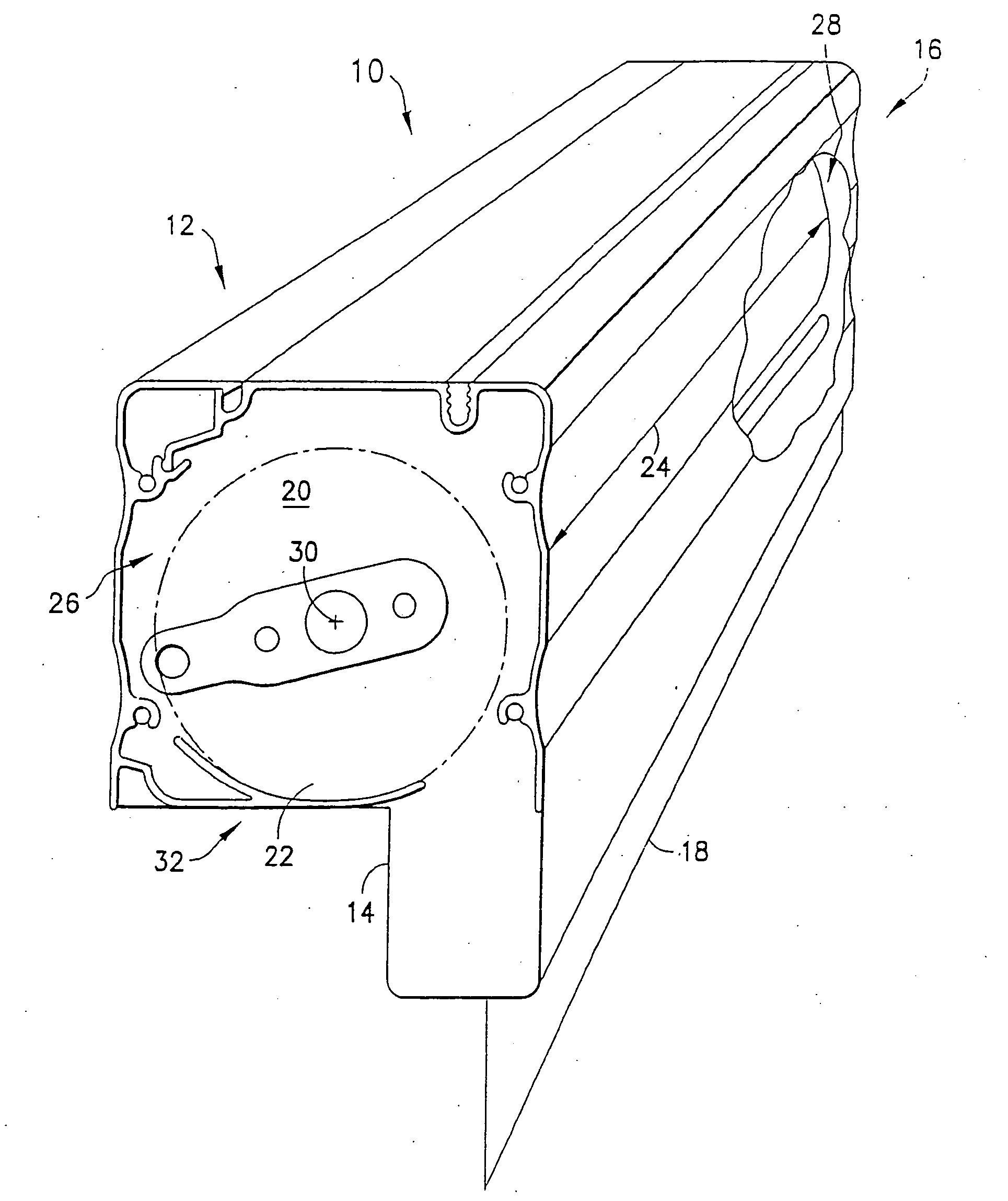
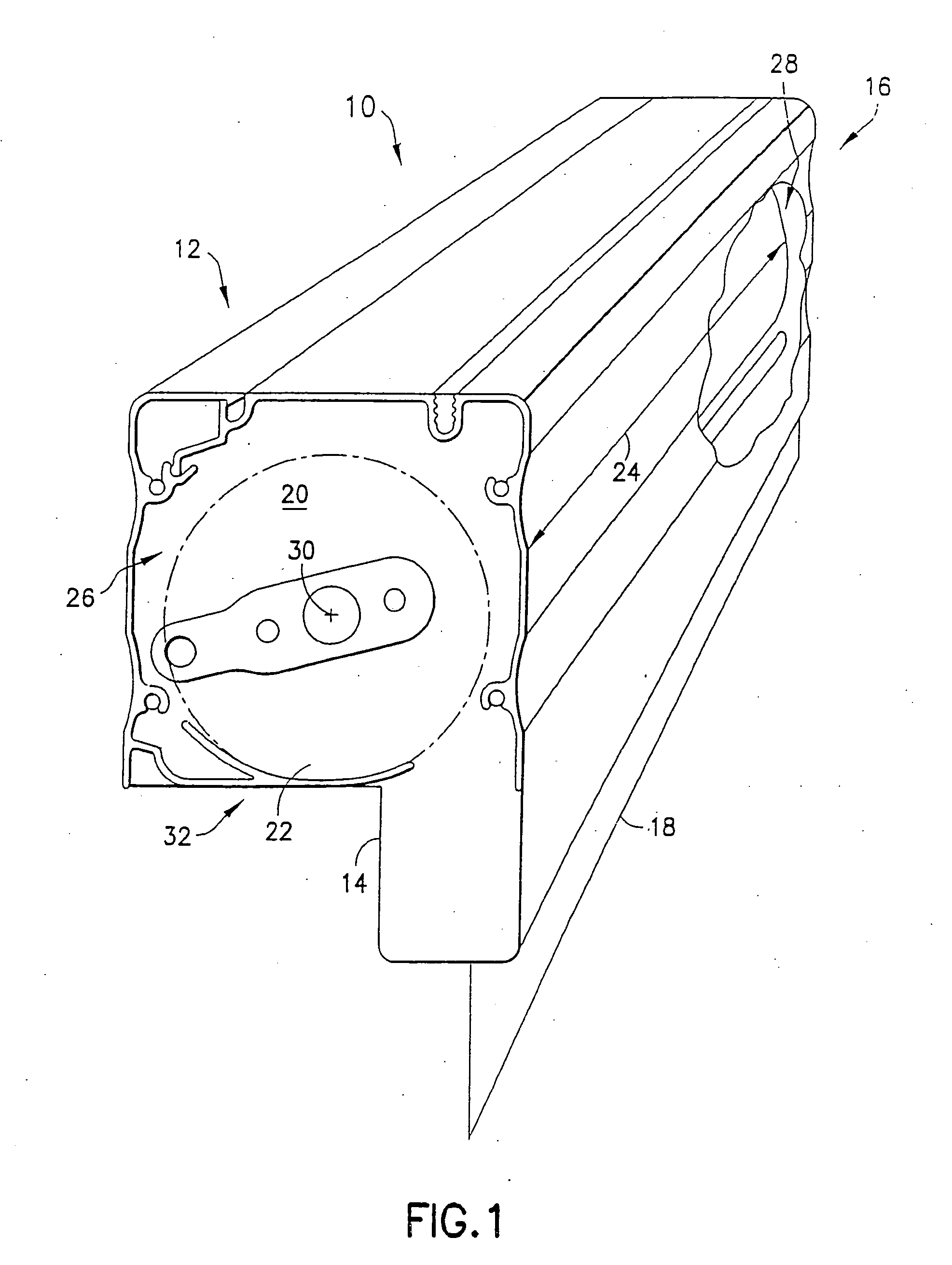
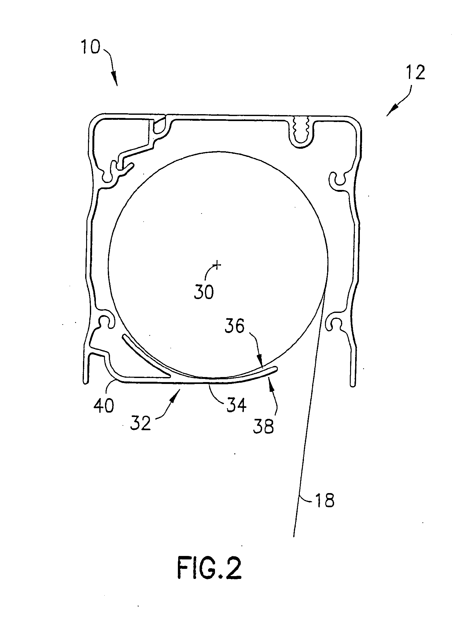
[0052]A roller tube support assembly in accordance with the present invention can include a first mount and a second mount opposite each other. The assembly can be configured to rotatably support a roller tube between the first mount and the second mount. The roller tube includes a body defining a length between a first end and a second end. The roller tube can be configured to support a sheet material wound around the roller tube body along the length of the body between the first and second ends of the body. Alternatively, the roller tube can be configured to support multiple widths of sheet material wound around the roller tube body to provide a single roller tube system for adjacent windows separated by mullions. A support cradle can be coupled to the assembly between the first and second mounts. The support cradle can be configured to support the roller tube. A biasing member is arranged to reduce a force of the roller tube in a direction towards the support cradle. By reducing...


PUM


Abstract

A support assembly is provided for a roller tube that holds sheet material. The support assembly has opposed first and second mounts adapted to support the roller tube when rotatably coupled to the mounts. The mounts can include slides having a slide member that slides within a slide bracket. A support cradle is disposed between the first and second mounts. The support cradle is configured to support the roller tube along a length thereof. Various spring elements can be arranged to apply a force to the roller tube in an upward direction when the roller tube is positioned to dispense material therefrom in a downward direction, thereby preventing the sheet material from telescoping and/or from dragging or binding against the support cradle as it winds and/or unwinds, while also keeping the material from being wound tighter at the ends than across the rest of the roller tube.

Description

[0001]This application is a continuation-in-part of co-pending U.S. patent application Ser. No. 11 / 086,819 filed on Mar. 22, 2005, which was a continuation-in-part of U.S. patent application Ser. No. 10 / 943,302 filed on Sep. 17, 2004, now U.S. Pat. No. 7,134,473, all incorporated herein by reference.BACKGROUND[0002]The present invention relates to the rolling and unrolling of sheet material for such uses as solar screens and awnings, image (e.g., video and movie) projection screens, blackout screens, and insect blocking screens and more particularly, to a roller tube assembly including a spring biased roller tube slide and integral support cradle for a roll-fed sheet material.[0003]Conventional roller tube systems make use of flexible sheet materials supported by elongated roller tubes. The roller tube, typically made from aluminum or steel, is rotatably supported and provides support for the flexible sheet material on the roller tube. Roller tube systems include manual and motorize...

Claims


Application Information

Patent Timeline
Patent Type & Authority Applications(United States)
IPC IPC(8): E06B9/34
CPCE04F10/0662E04F10/0677E04F10/0685E06B9/50E06B2009/1743G03B21/58
Inventor LUKOS, STEPHEN
Owner LUKOS STEPHEN
Why Eureka
Try Eureka