Energy recapture for an industrial vehicle

a technology for industrial vehicles and energy, applied in the direction of motor/generator/converter stoppers, dynamo-electric converter control, capacitor propulsion, etc., can solve the problems of reducing vehicle performance and effective operating time, reducing the overall productivity of electric vehicles, and losing productivity tim

Active Publication Date: 2008-11-27
HYSTER YALE GRP
View PDF25 Cites 71 Cited by
  • Summary
  • Abstract
  • Description
  • Claims
  • Application Information

AI Technical Summary

Benefits of technology

[0010]The foregoing and other objects, features and advantages of the invention will become more readily apparent from the following detailed description of a preferred embodiment of the invention which proceeds with reference to the accompanying drawings.

Problems solved by technology

The overall productivity of an electric vehicle is limited by an amount of energy that is stored in the vehicle battery.
Where the electric vehicle is operated for extended or multiple shifts, the battery typically needs to be recharged or replaced one or more times. This results in lost productivity time, and requires that charged replacement batteries are stocked and made available.
However, the increased size of the battery reduces vehicle performance and effective operating time due to the increased weight, and adds cost to the battery and vehicle purchase price.
Furthermore, many vehicle operations place a premium on vehicle operating space, such that any increase in battery size is limited by the maximum allowable battery compartment space available.
However, there are limits inherent in the chemical processes involved in charging a lead acid battery.
As a result, a lead acid battery cannot change from discharging to recharging fast enough and accept a high enough rate of recharge to recover a high percentage of regenerative energy.
Using the motor as a generator results in bursts of energy that tend to exceed the rate at which the battery may be recharged effectively.
A nearly fully charged battery, such as at the beginning of a shift, is particularly inefficient at absorbing the incoming energy during regenerative braking.

Method used


Image

  • Energy recapture for an industrial vehicle
  • Energy recapture for an industrial vehicle
  • Energy recapture for an industrial vehicle

Examples


Embodiment Construction

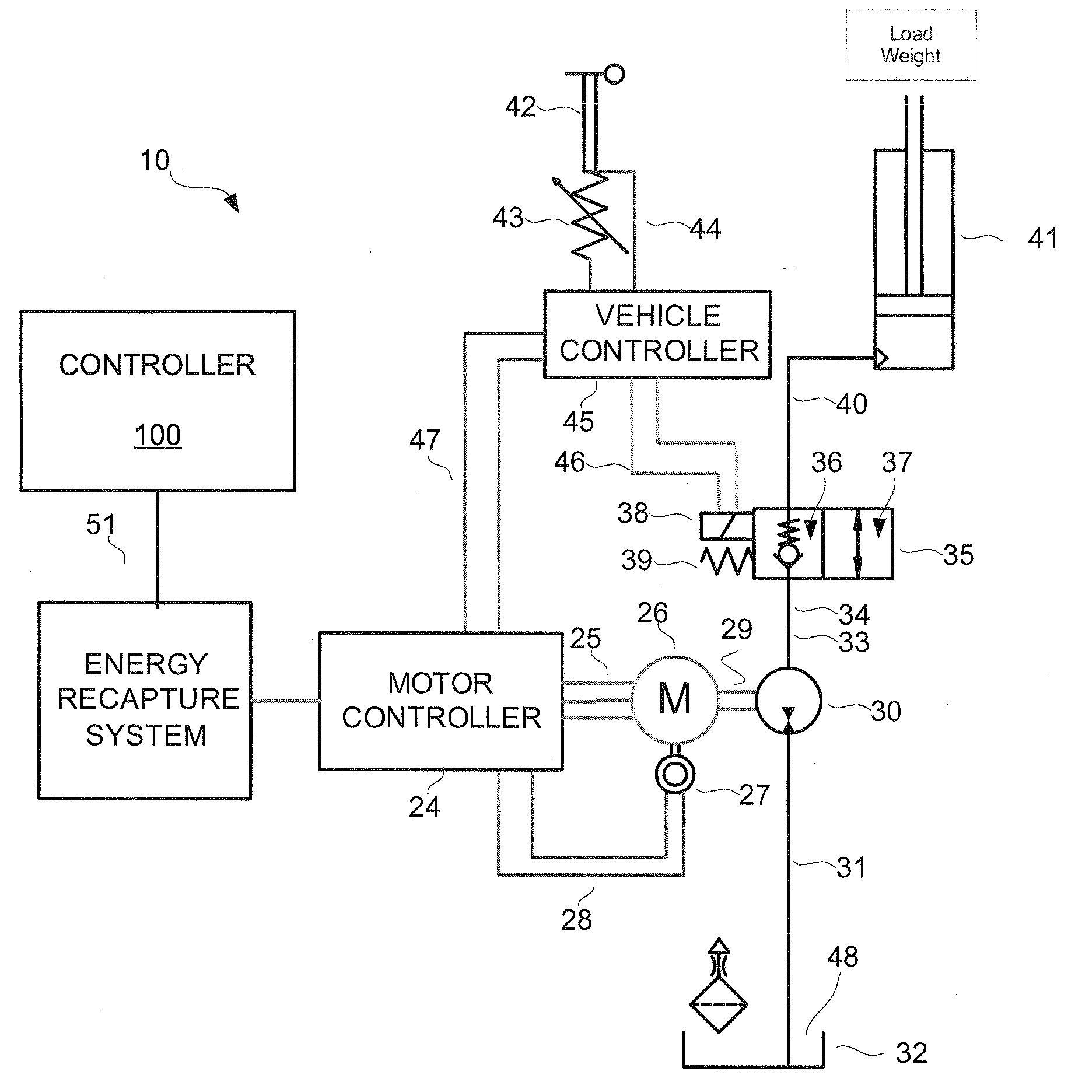
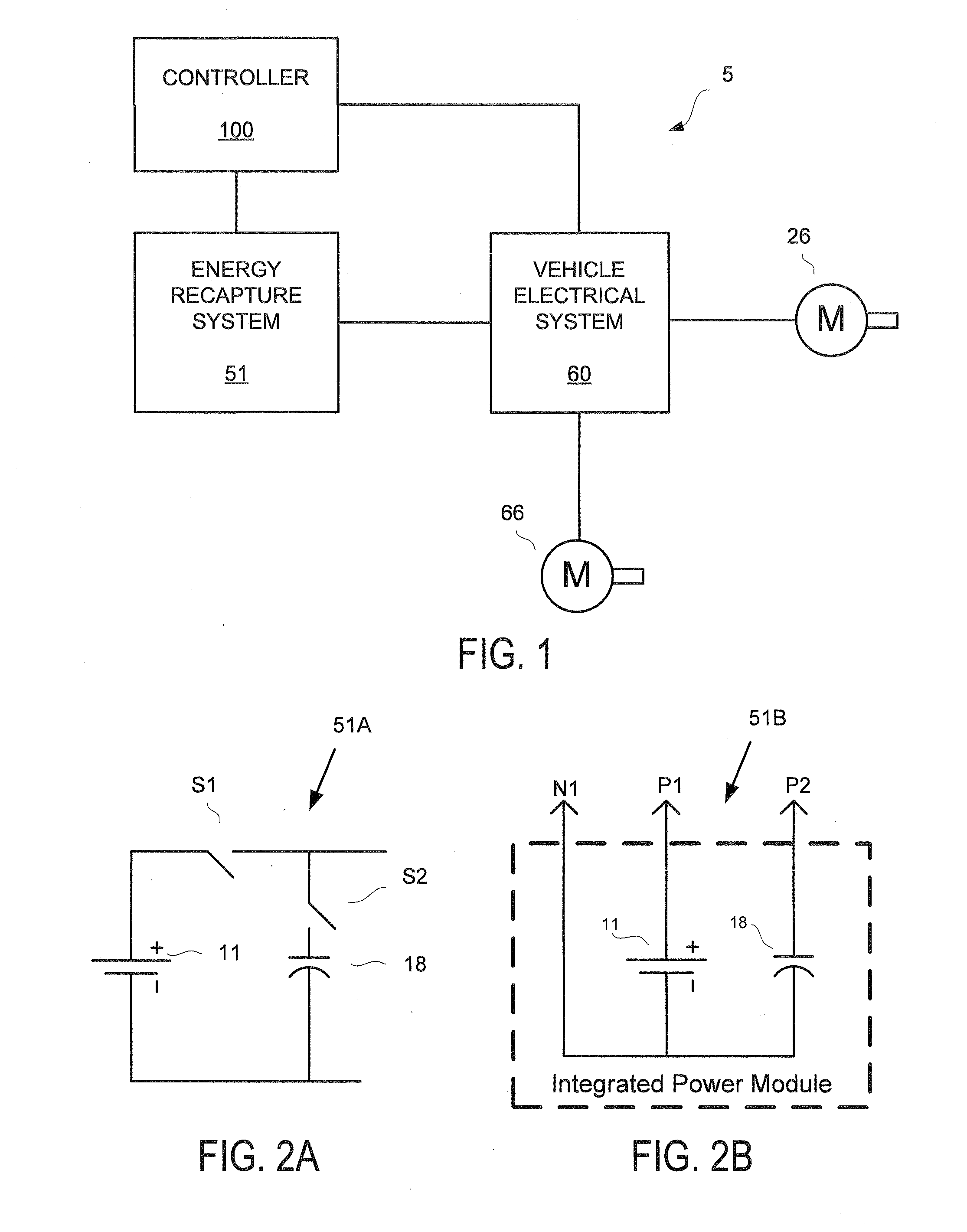
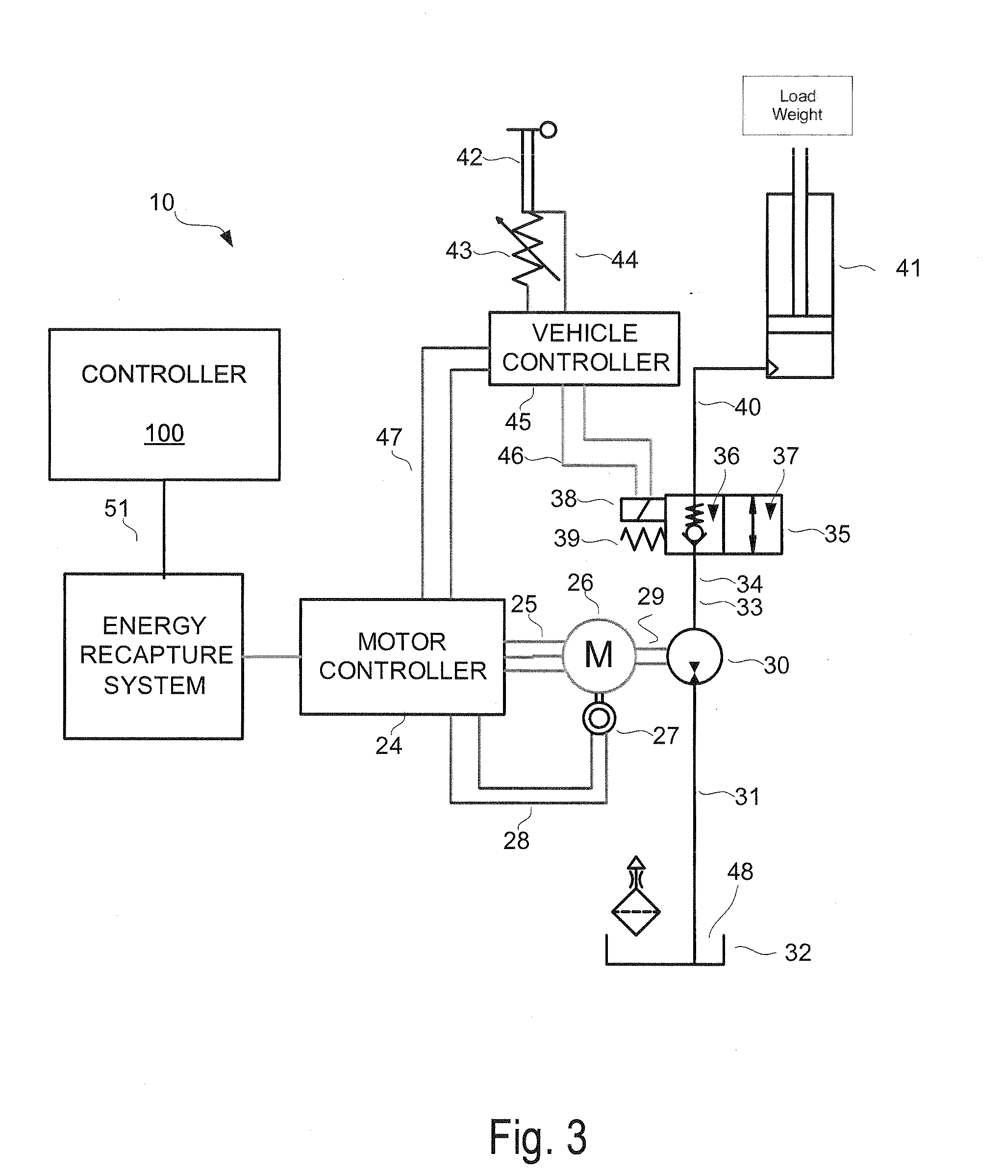
[0020]FIG. 1 illustrates a simplified block diagram of an industrial vehicle 5 comprising a vehicle electrical system 60 and an energy recapture system 51. The vehicle electrical system 60 is shown as including or being operatively connected to one or more electrical motors 26, 66. The one or more motors may provide power for a variety of vehicle operations, and may include a hoist motor 26, a traction motor 66, or an auxiliary motor (not shown). The one or more motors 26, 66 may operate as electrical generators during an energy recapture event, such that electricity generated by the one or more motors 26, 66 may be supplied to and stored in the energy recapture system 51.

[0021]Energy provided by the one or more motors 26, 66 or by the energy recapture system 51 may be used for a number of different vehicle operations or functions. For example, energy requests or demands may be made for one or more of the following: vehicle traction, hoist, lighting, horn, backup alarm, operator com...


PUM


Abstract

A system for capturing regenerative energy includes a battery configured to provide power for a traction motor and other operations of a vehicle and a capacitor connected to the battery. An auxiliary motor is configured to operate as a generator during a regenerative energy operation. The system further includes a controller configured to direct the regenerative energy to the capacitor during the regenerative energy operation and discharge the capacitor to provide power to the traction motor or for the other operations of the vehicle.

Description

[0001]This application claims priority to U.S. Provisional Application 60 / 939,336 filed on May 21, 2007, which is herein incorporated by reference in its entirety.BACKGROUND[0002]Electric vehicles typically utilize an electric motor to provide for traction that provides horizontal movement of the vehicle. Batteries installed on the electric vehicle provide the electric motor with a source of electrical energy. The electric vehicle and associated motor or motors may be configured to operate using either an AC (alternating current) or DC (direct current) electrical system. A rate of energy discharge from the battery during operation of the vehicle depends on a number of conditions including vehicle travel speed, weight of load being transported, efficiency of the electrical system, and even operating temperatures, among others.[0003]The overall productivity of an electric vehicle is limited by an amount of energy that is stored in the vehicle battery. Where the electric vehicle is ope...

Claims


Application Information

Patent Timeline
Patent Type & Authority Applications(United States)
IPC IPC(8): H02J7/00H02P3/14
CPCB60L7/24B60L11/005H02J7/1423H02J7/345Y02T10/7016Y02T10/7022B60L50/40Y02T10/70
Inventor DAVIS, JAMES W.MCGOLDRICK, KEVIN J.FITZSIMMONS, ALAN H.NEIL, ROBERT M.ROWLEY, JOHN
Owner HYSTER YALE GRP
Why Eureka
Try Eureka