Methods, circuits, and systems to select memory regions

Active Publication Date: 2008-11-27
MICRON TECH INC
View PDF18 Cites 12 Cited by
  • Summary
  • Abstract
  • Description
  • Claims
  • Application Information

AI Technical Summary

Problems solved by technology

One operation that tends to consume power at a substantial rate is the refresh of memory cells in the DRAM device.
Since refresh essentially involves reading data bits from and writing data bits to a large number of memory cells, refresh tends to be a particularly power-hungry operation.
Although the techniques for refreshing less than all of the memory cells can substantially reduce the rate of power consumption, it can nevertheless require a substantial amount of power to refresh the cells that are to be refreshed.
Additionally, although a user is able to select a partial self-refresh mode instead of the full self-refresh mode to reduce the power consumption rate, the memory cells selected for the partial self-refresh are hardwired in the device at the time of manufacture and cannot be changed by the user.
Therefore, if the selected partial self-refresh region contains inherent defects, another region of memory that can be more efficiently refreshed cannot be reselected.
When a certain number of memory cells become defective such as, for example, as a result of a shorted memory cell capacitor, delays to the memory access may result due to the defective memory cell.
However, substantial additional circuitry must be provided to redirect memory accesses to redundant memory cells, which adds further delays to refresh operations.

Method used


Image

  • Methods, circuits, and systems to select memory regions
  • Methods, circuits, and systems to select memory regions
  • Methods, circuits, and systems to select memory regions

Examples


Embodiment Construction

[0011]The explicitly disclosed embodiments of the present invention are directed to, for example, improving the performance of self refresh operations in memory devices, systems and methods. Certain details are set forth below to provide a sufficient understanding of the embodiments of the invention. However, it will be clear to one skilled in the art that embodiments of the invention may be practiced without these particular details. In other instances, well-known circuits, circuit components, control signals, and timing protocols have not been shown in detail in order to avoid unnecessarily obscuring the embodiments of the invention.

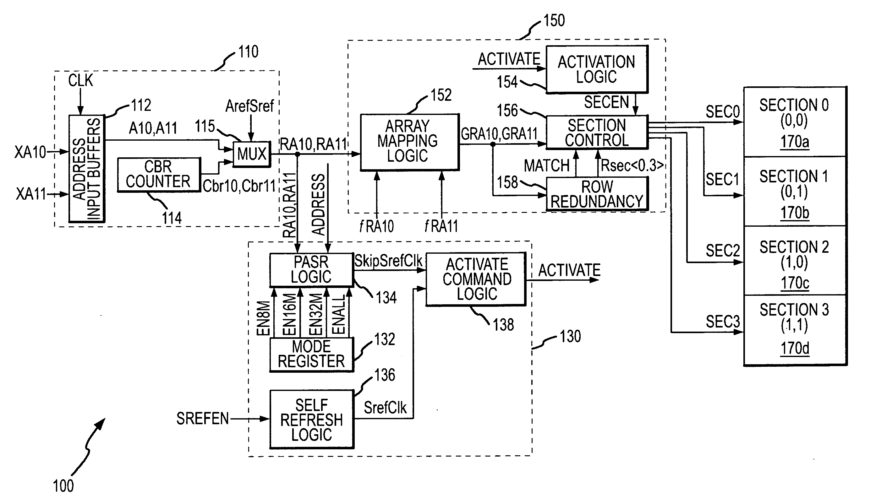
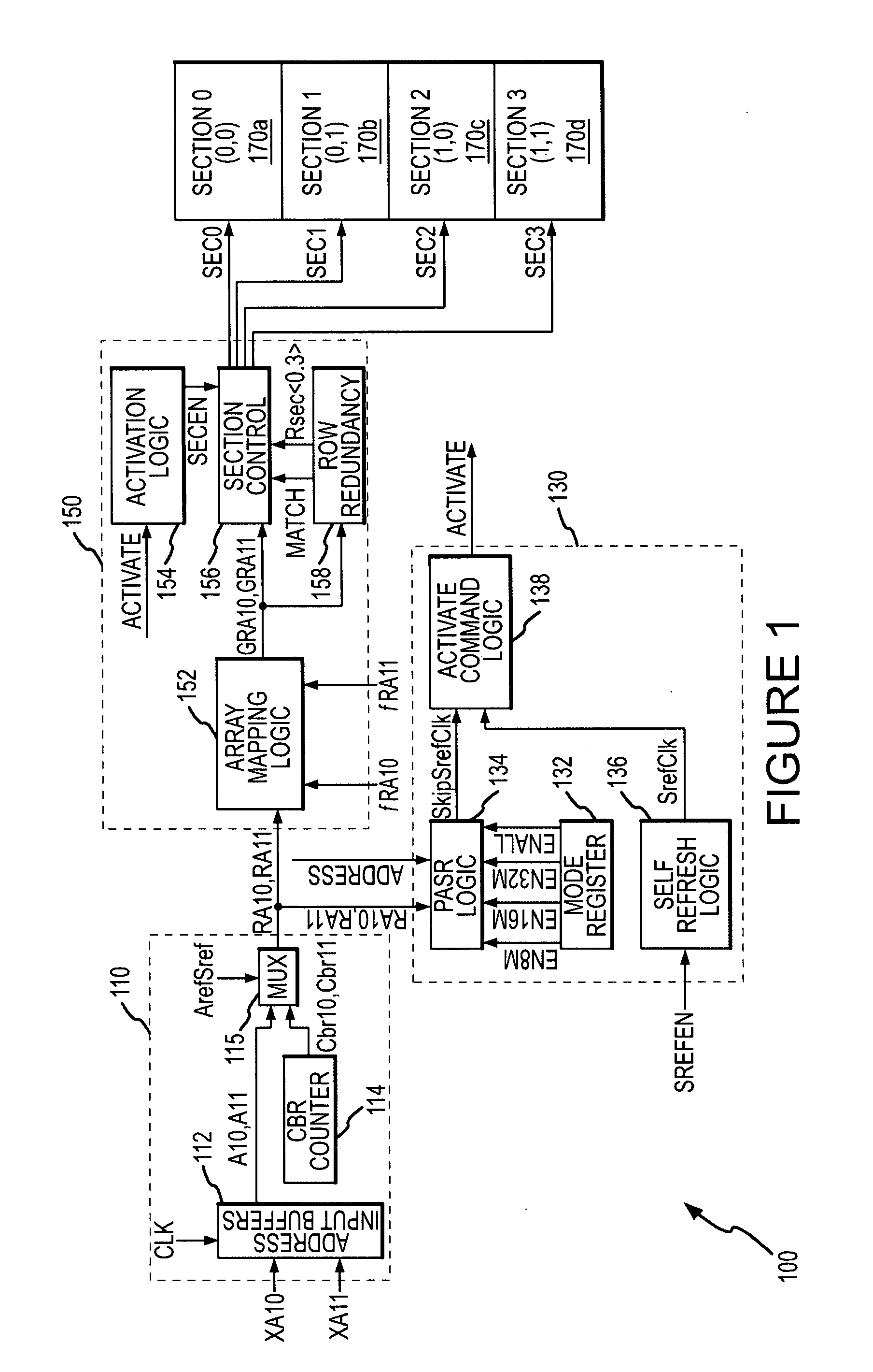
[0012]FIG. 1 is a block diagram of a DRAM memory device 100 showing an array mapping logic module 152 for mapping regions of a memory array 170 according to an embodiment of the invention. The DRAM memory device 100 is shown in simplified form, it being understood that DRAM devices typically include a large number of other components, which have been o...


PUM


Abstract

Embodiments for selecting regions of memory are described. For example, in one embodiment a memory device having an array of memory cells includes an array selection block. The array selection block receives an input signal indicative of a region in the array of memory cells. The array selection block generates a selection signal to map the region to at least one physical location in the array of memory cells, based on the detection of the number of defects in that location.

Description

TECHNICAL FIELD[0001]Embodiments of the invention relate to integrated circuits, more particularly to selecting memory regions in memory devices such as to improve the performance of self refresh operations.BACKGROUND OF THE INVENTION[0002]A variety of operations are performed in memory devices, such as dynamic random access memory devices (“DRAM”), each of which affects the rate at which the memory device consumes power. One operation that tends to consume power at a substantial rate is the refresh of memory cells in the DRAM device. As is well-known in the art, DRAM memory cells, each of which essentially consists of a capacitor, must be periodically refreshed to retain data stored in the DRAM device. Refresh is typically performed by reading data bits from the memory cells in each row of a memory cell array and then writing those same data bits back to the same cells in the row. This refresh is generally performed on a row-by-row basis at a rate needed to keep charge stored in th...

Claims


Application Information

Patent Timeline
IPC IPC(8): G11C7/00
CPCG06F12/02G06F2212/1028G11C8/12G11C11/406Y02B60/1225G11C11/40622G11C11/4082G11C11/4087G11C11/40615Y02D10/00G11C11/401G11C11/402G11C11/403G11C11/408
Inventor SMITH, SCOTT E.
Owner MICRON TECH INC
Why Eureka
Try Eureka