Image encoding apparatus and control method thereof

a technology of image encoding and control method, which is applied in the field of image encoding technique, can solve the problems of deteriorating encoding efficiency depending on images, jpeg encoding readily generating mosquito noise, and jpeg encoding readily causing block distortion (block-shaped noise), so as to achieve the effect of greatly reducing the amount of encoded data

Inactive Publication Date: 2008-11-27
CANON KK
View PDF15 Cites 56 Cited by
  • Summary
  • Abstract
  • Description
  • Claims
  • Application Information

AI Technical Summary

Benefits of technology

[0022]According to the present invention, a plurality of encoding processing units respectively sort pixel data in each block according to different scan start positions

Problems solved by technology

However, for images including characters, line arts, and the like, JPEG encoding readily generates mosquito noise due to loss of high frequency components of images.
Also, JPEG encoding readily causes block distortion (block-shaped noise) due to l

Method used


Image

  • Image encoding apparatus and control method thereof
  • Image encoding apparatus and control method thereof
  • Image encoding apparatus and control method thereof

Examples


first embodiment

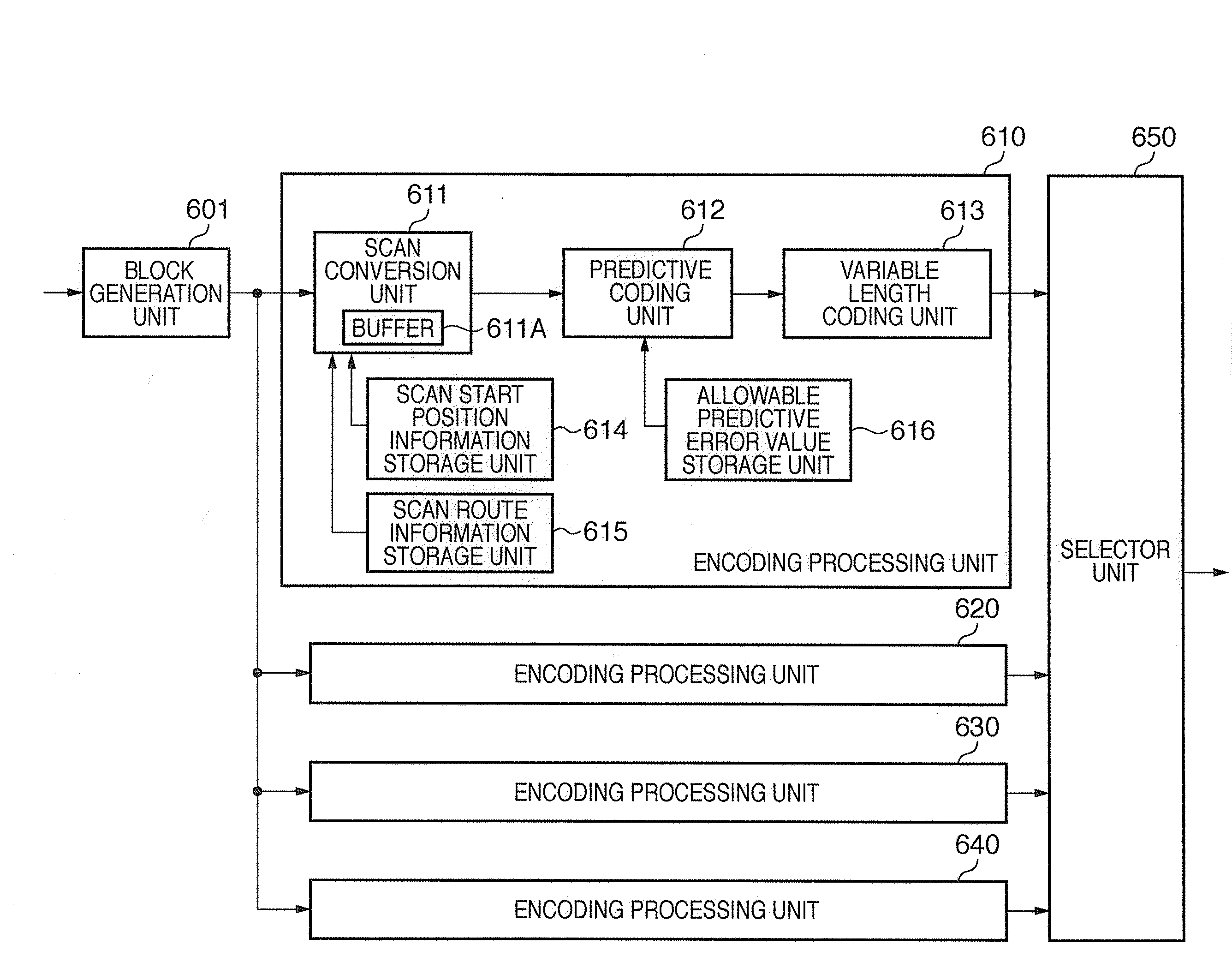
[0039]FIG. 6 is a block diagram showing the arrangement of an image encoding apparatus according to the first embodiment.

[0040]A block generation unit 601 inputs image data defined by m×n pixels (to be referred to as image block data hereinafter) from image to be encoded. Assume that the inputting order of image block data is a raster scan order for respective blocks. For the sake of simplicity, an image block has a size of 8×8 pixels in the description of this embodiment. Also, a supply source of image data to be encoded is an image scanner. However, the supply source may be a storage medium which stores that image data, or a rendering unit which generates image data based on print data. Hence, the types of supply sources are not particularly limited.

[0041]The apparatus of this embodiment comprises a plurality of encoding processing units which receive image block data and generate encoded data. In FIG. 6, reference numerals 610, 620, 630, and 640 denote such encoding processing un...

second embodiment

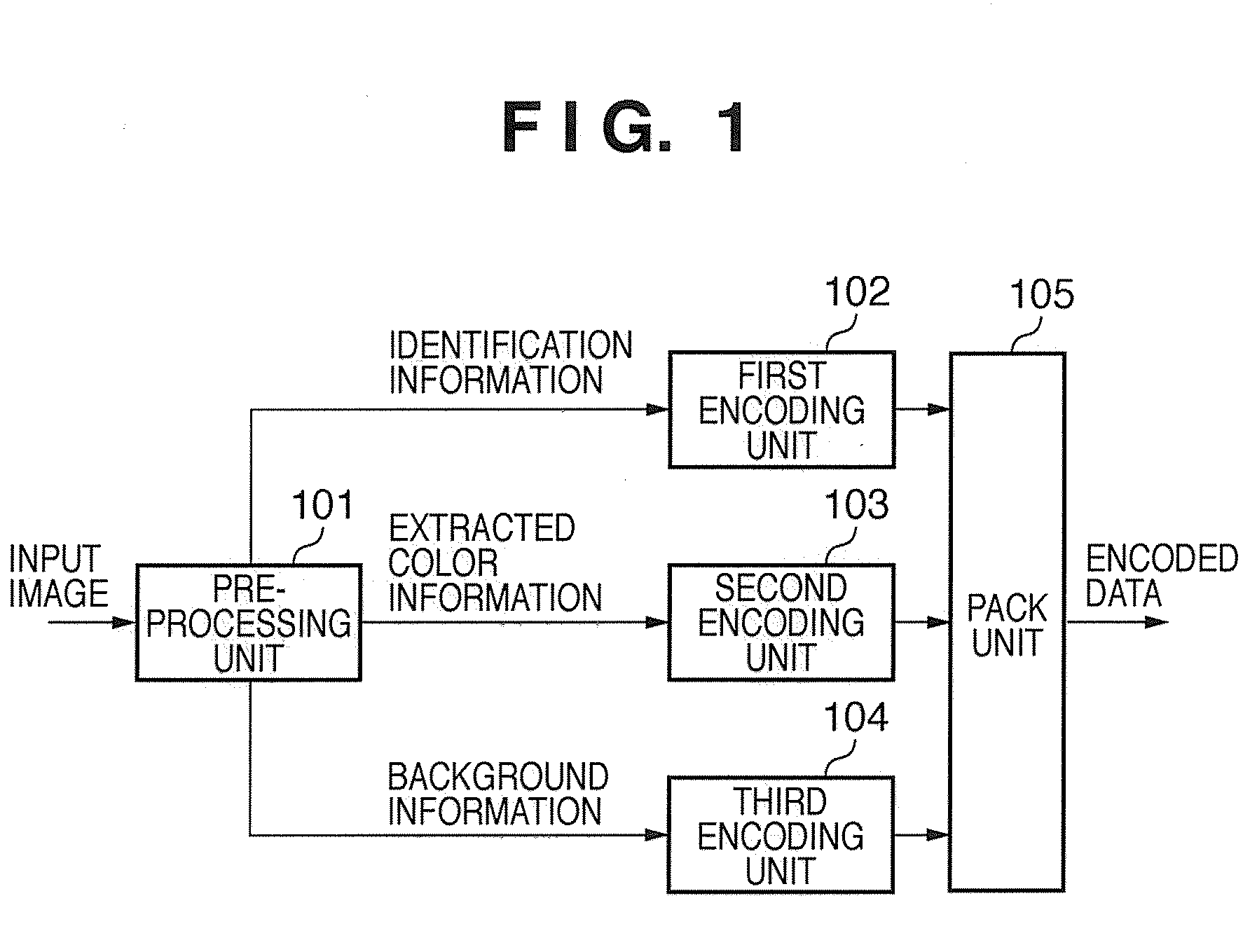
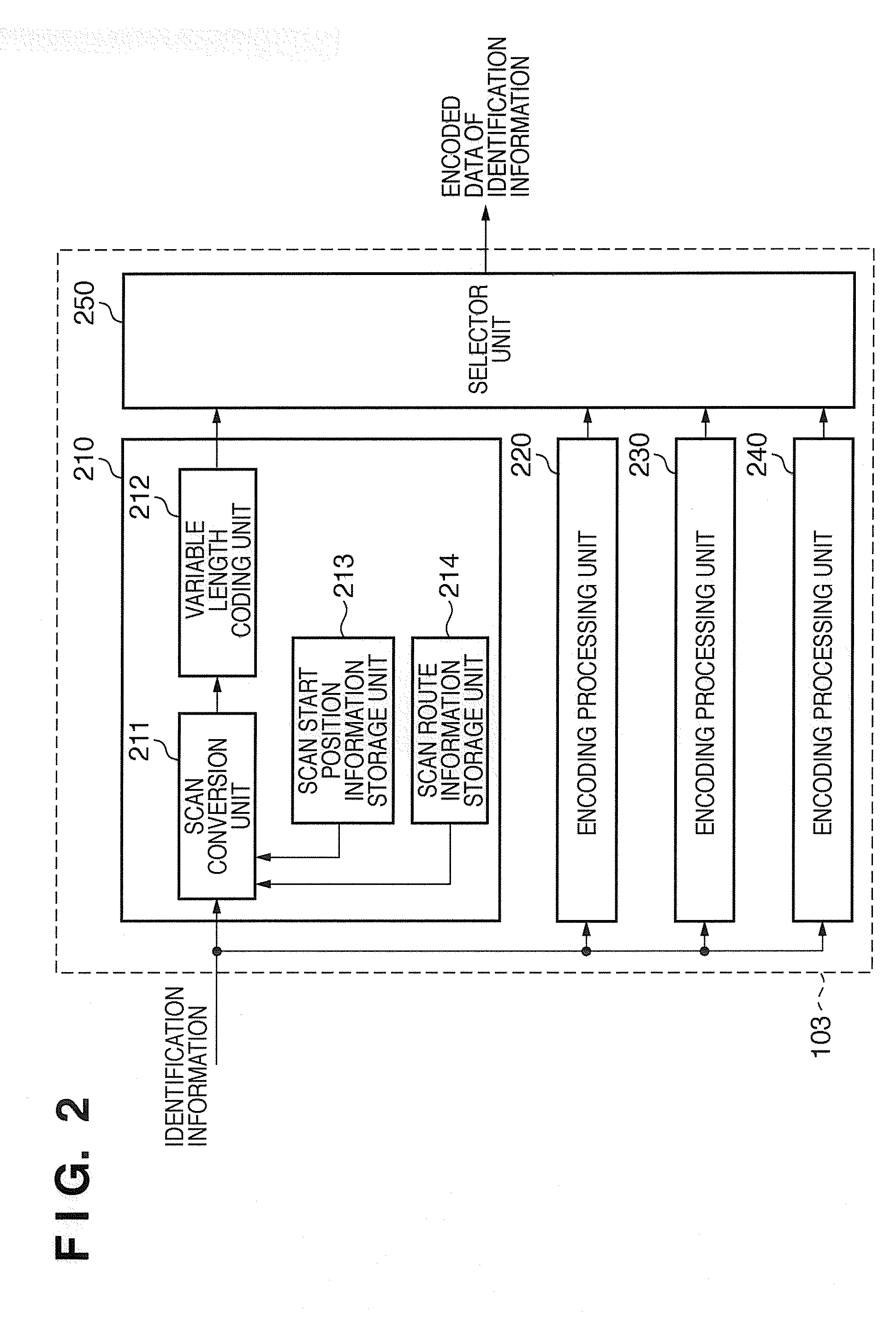
[0074]The second embodiment will be described below. FIG. 1 is a block diagram showing the arrangement of an image encoding apparatus according to the second embodiment.

[0075]Referring to FIG. 1, a pre-processing unit 101 receives image data for respective blocks, and executes a series of processes until an image in each inputted block is separated into an extracted color part and background part (non-extracted color part). In this embodiment, the size of each block is defined by 8×8 pixels. However, the sizes of 16×16 pixels, 32×32 pixels, and the like may be used. In this embodiment, assume that the value of each pixel of inputted image data indicates a density.

[0076]An example of the separation method of an extracted color part and background part will be described below.

[0077]The pre-processing unit 101 calculates an average of densities of all pixel data in a block. The pre-processing unit 101 classifies the densities of the pixel data into a pixel group (to be referred to as a...

third embodiment

[0103]Note that the first embodiment has explained the example using the scan patterns shown in FIGS. 7A to 7D, and the second embodiment has explained the example using the scan patterns shown in FIGS. 3A to 3D. However, the present invention is not limited to these scan patterns. In short, any start positions and scan routes can be set depending on information to be set in scan start information storage units and scan route information storage units.

[0104]For example, scan start positions and scan routes shown in FIGS. 5A to 5D may be adopted.

[0105]FIG. 5A shows an example in which the upper left corner is set as the scan start position, and a zigzag scan is made in the down direction. FIG. 5B shows an example in which the lower left corner is set as the scan start position, and a zigzag scan is made in the right direction. FIG. 5C shows an example in which the lower right corner is set as the scan start position, and a zigzag scan is made in the up direction. FIG. 5D shows an exa...


PUM


Abstract

According to this invention, encoded data are generated by sorting pixel data in a block according to different scan start positions and different scan routes upon generating encoded data for respective blocks, and encoded data with a smallest data amount of these encoded data is outputted. To this end, a block generation unit inputs blocks each defined by 8×8 pixels from image data to be encoded. Four encoding processing units respectively sort inputted 8×8 pixels according to the information stored in scan start position information storage units and scan route information storage units. The respective encoding processing units generate encoded data based on the sorted pixel data. A selector selects and outputs encoded data with a smallest data size from those generated by the encoding processing units.

Description

BACKGROUND OF THE INVENTION[0001]1. Field of the Invention[0002]The present invention relates to an encoding technique of an image.[0003]2. Description of the Related Art[0004]Conventionally, as a method of encoding an image, methods such as JPEG encoding using orthogonal transformation and the like are available. JPEG encoding will be briefly described below. An image is divided into blocks of 8×8 pixels, and each block undergoes DCT (discrete cosine transformation). 8×8 DCT coefficient values obtained by the DCT are quantized using a quantization table. Since the quantization table normally has larger quantization step widths for higher frequency components, quantized values are smaller and the frequency of occurrence of “0” becomes higher for higher frequency components.[0005]Subsequently, the quantized values are encoded. In this case, different encoding processes are applied to DC and AC components. DC components undergo predictive coding since they have strong correlation betw...

Claims


Application Information

Patent Timeline
IPC IPC(8): G06K9/36
CPCH04N19/105H04N19/176H04N19/102H04N19/60H04N19/593H04N19/93H04N19/186H04N19/146H04N19/182H04N19/17H04N19/12
Inventor NAKAGAWA, AKIOISHIKAWA, HISASHIMISE, RYOKO
Owner CANON KK
Why Eureka
Try Eureka