Compressor driving torque estimating apparatus
a compressor and torque technology, applied in the field of torque estimation devices, can solve problems such as discrepancy between the estimated drive torque and the actual compressor drive torque, and the unsuitable estimation of the compressor torque is an important issu
- Summary
- Abstract
- Description
- Claims
- Application Information
AI Technical Summary
Benefits of technology
Problems solved by technology
Method used
Image

Examples
first embodiment
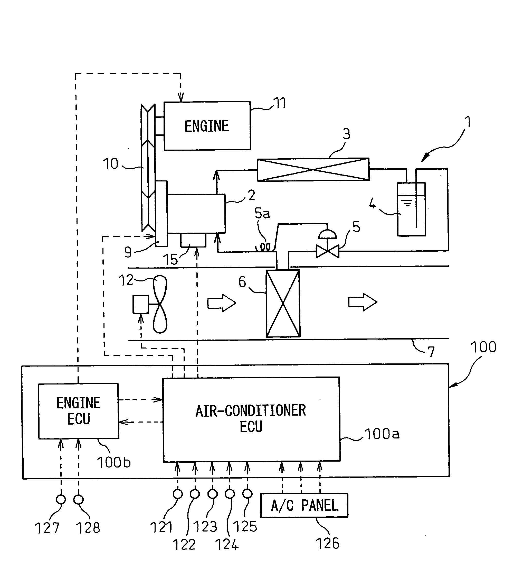
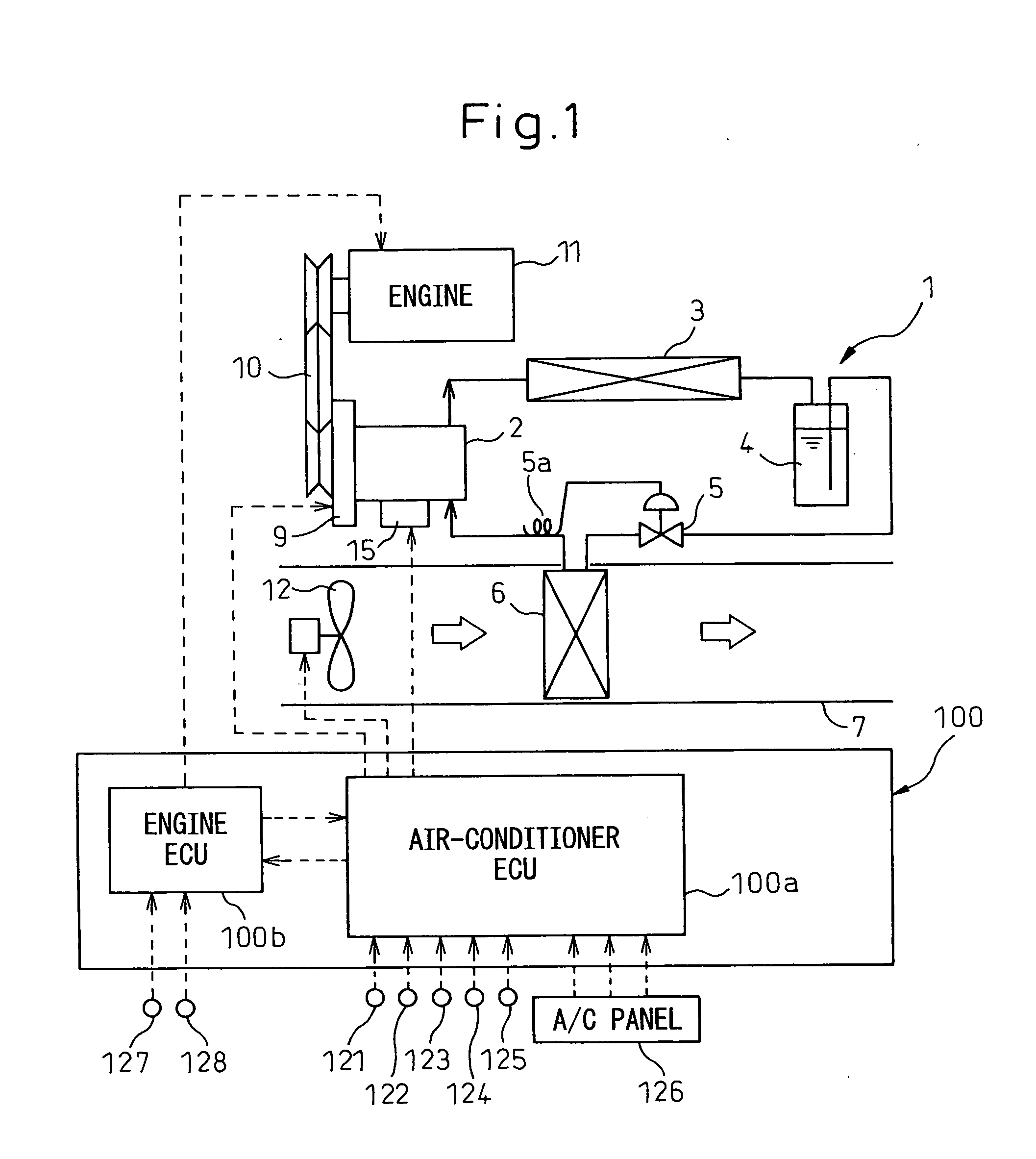
[0033]Below, a first embodiment of the present invention will be explained based on FIG. 1 to FIG. 5. The present embodiment is an application of the present invention to an idling speed control device for a vehicle. The vehicle of the present embodiment uses as a refrigerant compressor of a vehicular air-conditioning system a variable capacity type compressor 2 obtaining drive power from an engine 11 for operating the vehicle. The idling speed control device is designed to control the engine speed based on an estimated drive torque STrk of a later mentioned variable capacity type compressor 2.
[0034]FIG. 1 is a schematic view of the overall configuration of the present embodiment. The engine 11 has an intake pipe (not shown). Inside the intake pipe, a throttle valve (not shown) is arranged. The throttle valve adjusts the amount of air sucked into the intake pipe in accordance with the opening degree accompanying depression of an accelerator pedal of the vehicle. Further, as is well ...
second embodiment
[0110]A second embodiment of the present invention will be explained. In the second embodiment, only the parts different from the above first embodiment will be explained.
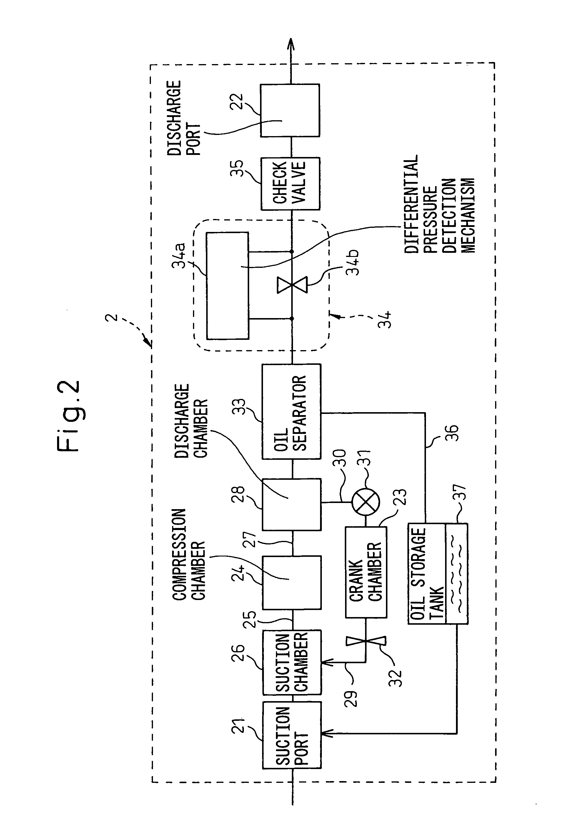
[0111]In the above first embodiment, the compressor estimated drive torque STrk is calculated in the case of using a variable capacity type compressor having a second control valve 32 for the variable capacity device 15 of the variable capacity type compressor 2. In the second embodiment, the compressor estimated drive torque STrk is calculated in the case of using a variable capacity type compressor 2 not having the second control valve 32.
[0112]The variable capacity type compressor 2 in the present embodiment does not have the second control valve 32, so the effect of the suction refrigerant pressure Ps on the compressor torque increase characteristic is small.
[0113]For this reason, it is possible to store control maps based on the differential pressure between the discharge refrigerant pressure Pd and the suctio...
third embodiment
[0115]Next, a third embodiment of the present invention will be explained. In the third embodiment, only parts different from the above first embodiment and second embodiment will be explained.
[0116]In the above first embodiment and second embodiment, the estimated drive torque STrk of the variable capacity type compressor 2 in the transitory state right after compression start of the compressor 2 was calculated, but in the present embodiment, the estimated drive torque STrk of the variable capacity type compressor 2 is calculated in the transitory state after starting the operation for stopping operation of the variable capacity type compressor 2.
[0117]At step S2 of FIG. 2, when the OFF signal of the air-conditioner switch is detected in the operation signals of the air-conditioner operation switches, the one control map selected from the plurality of maps in the calculation of the estimated drive torque of step S4 is changed to a control map for the time of start of stopping the o...
PUM
 Abstract
Description
Claims
Application Information
PatSnap Eureka turns technology decisions into work you can execute. Powered by our Innovation Knowledge Graph, it runs expert workflows across engineering, life sciences, materials and intellectual property. Get your review-ready output in minutes.


