Surgical jaw instrument having a slide system

Active Publication Date: 2012-04-26
OLYMPUS WINTER & IBE
View PDF8 Cites 12 Cited by
  • Summary
  • Abstract
  • Description
  • Claims
  • Application Information

AI Technical Summary

Benefits of technology

[0011]It is thereby advantageous that the bearing position is designed as groove mounting that can not only absorb extremely high forces, but also makes a better electric isolation possible of gliding rod and jaw piece.
[0012]Preferably, at least one of the jaw pieces has an electrode. With it, the jaw instrument can be used, for example, for coagulation, whereby preferably, of course, both jaw pieces

Problems solved by technology

In particular, in the case of bipolar design, i.e. with different terminals at the two jaw components of a forceps or a scissors, enormous technical problems arise at the joints between the jaw components with respect to the electric isolation.
The known design that was cited at the beginning has, however, also a significant disadvantage.
But the reverse motion, namely the opening motion of the jaw pieces cannot take place by an actuation of the thrust tube.
But the resilient forces

Method used


Image

  • Surgical jaw instrument having a slide system
  • Surgical jaw instrument having a slide system

Examples


Embodiment Construction

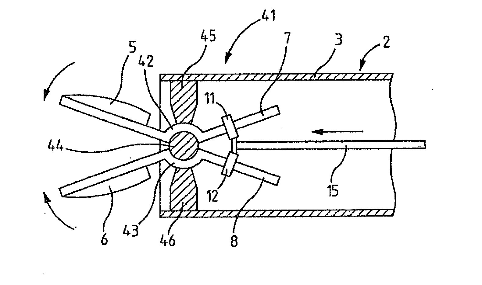
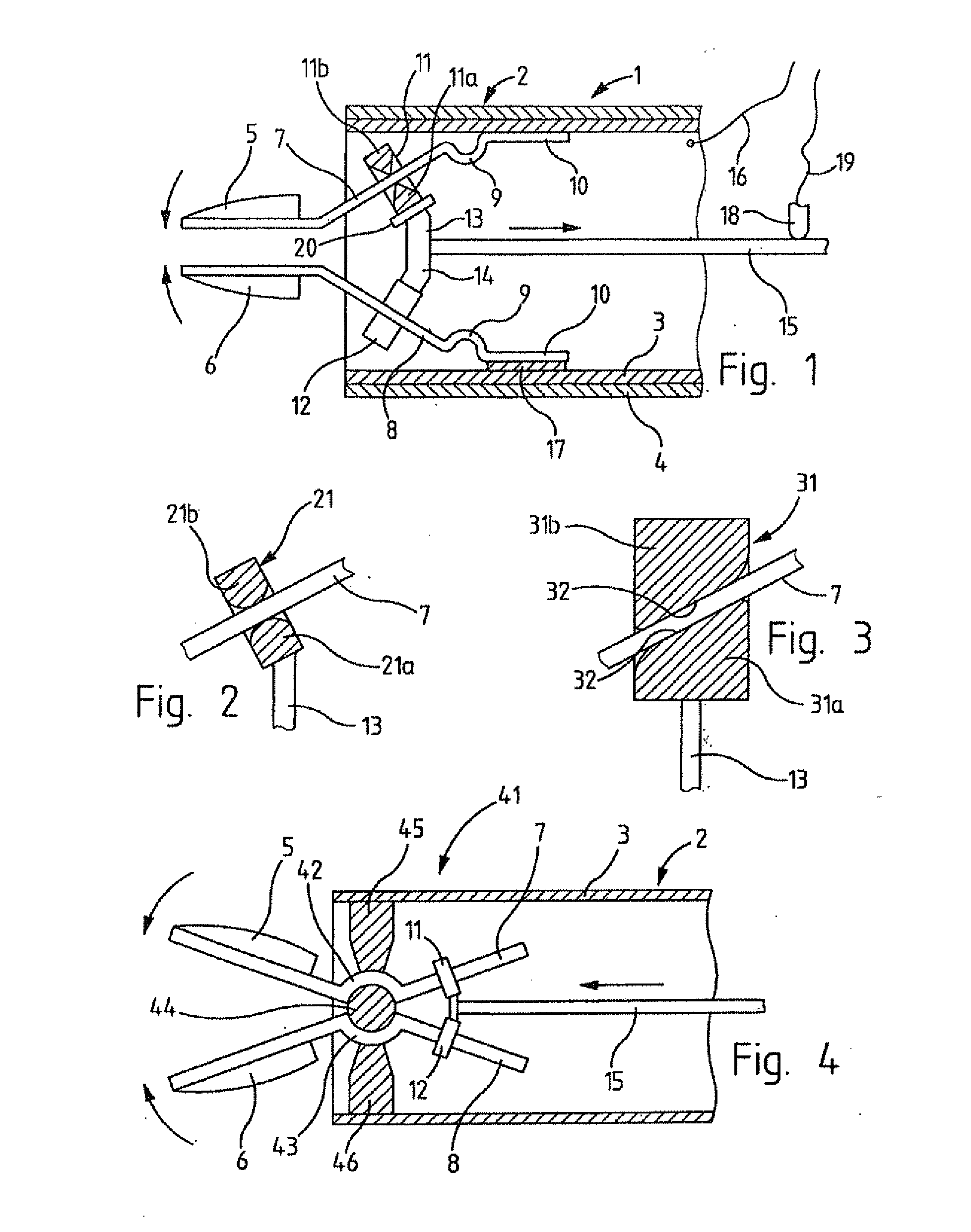
[0018]FIG. 1 shows a surgical jaw instrument 1 with a shaft 2 that consists of a metal tube 3 with an isolating covering 4.

[0019]Two jaw pieces 5, 6 are located projecting over the distal end of shaft 2, that are mounted at the distal ends of two sliding rods 7, 8 that are converging slanted in distal direction. The proximal ends of the sliding rods are fastened articulated with joints 9 at end pieces 10, which are mounted at metal tube 3.

[0020]Joints 9 allow a deviating motion of sliding rods 7, 8. Joints 9 can, for example, be designed as hinged joints with bearing pin, in the preferred embodiment shown in FIG. 1, however, they are designed as bendable spring elements that make an integral connection between jaw pieces 5, 6 and end pieces 10 possible.

[0021]Sliding members 11, 12 engage with sliding rods 7, 8, of which sliding member 11 is shown in cross section in FIG. 1. Both sliding members 11, 12 can be designed identically. As can be seen on sliding element 11, it has two slid...


PUM


Abstract

A surgical jaw instrument having two jaw pieces mounted at the distal end section of a shaft for relative reciprocal displacement, whereby at each displaced jaw piece a sliding rod is fastened at an incline to the axis of the shaft, to which a displaceable sliding element can be connected parallel to the axis of the shaft in such a way that upon displacement of the sliding element, the jaw pieces are relatively reciprocally displaced wherein a second sliding element is mounted at the first sliding element, diametrically opposed relative to the sliding rod.

Description

BACKGROUND OF THE INVENTION[0001]I. Field of the Invention[0002]The invention relates to a surgical jaw instrument.[0003]II. Description of the Related Art[0004]Jaw instruments of this type are known, for example, from U.S. Pat. No. 6,190,386 B1 and U.S. Pat. No. 4,819,633 A. In both designs, the sliding rods are located diverging in distal direction. The distal edge of a thrust tube that can be displaced in the axial direction of the shaft is the sliding element.[0005]The advantage of this known solution lies in the special simplicity of the design, whereby in particular, the complicated joint between the jaw components is avoided, as it is used in most forceps designs and scissors designs. This also results in an additional important advantage, namely, the simpler electric isolation for forceps provided with electrodes that are used, for example, for vascular electrocoagulation. In particular, in the case of bipolar design, i.e. with different terminals at the two jaw components o...

Claims


Application Information

Patent Timeline
IPC IPC(8): A61B17/00
CPCA61B17/29A61B18/1445A61B2018/00083A61B2017/2936A61B2017/2933A61B2017/2937
Inventor MIERSCH, HANNES
Owner OLYMPUS WINTER & IBE
Why Eureka
Try Eureka