Eureka AIR delivers breakthrough ideas for toughest innovation challenges, trusted by R&D personnel around the world.

Wafer chuck having thermal plate with interleaved heating and cooling elements

a technology of thermal plates and chucks, which is applied in the field of wafer chucks, can solve the problems of chucks made of softer materials, prone to distort, and particularly difficult requirements, and achieves low electrical capacitance, high voltage or, and cost saving for users.

Inactive Publication Date: 2005-10-06
TEMPTRONIC
View PDF5 Cites 12 Cited by
  • Summary
  • Abstract
  • Description
  • Claims
  • Application Information

AI Technical Summary

Benefits of technology

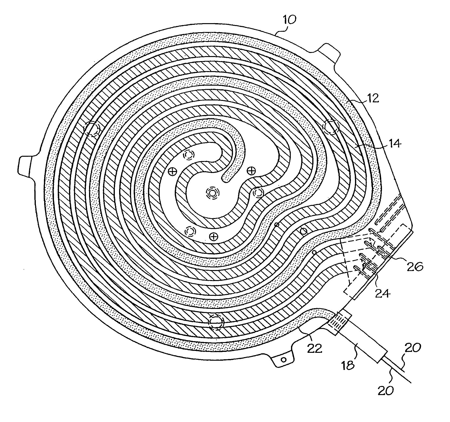
[0004] The thermal plate assembly of the invention can be a layer in the workpiece chuck. Because the heating and cooling elements occupy the same horizontal plane of the chuck, the heating and cooling are uniform across the top surface of the chuck where the workpiece, i.e., wafer, is supported. Also, because the heating and cooling elements are coplanar, substantial distortion and warping of the chuck and workpiece over temperature are eliminated.
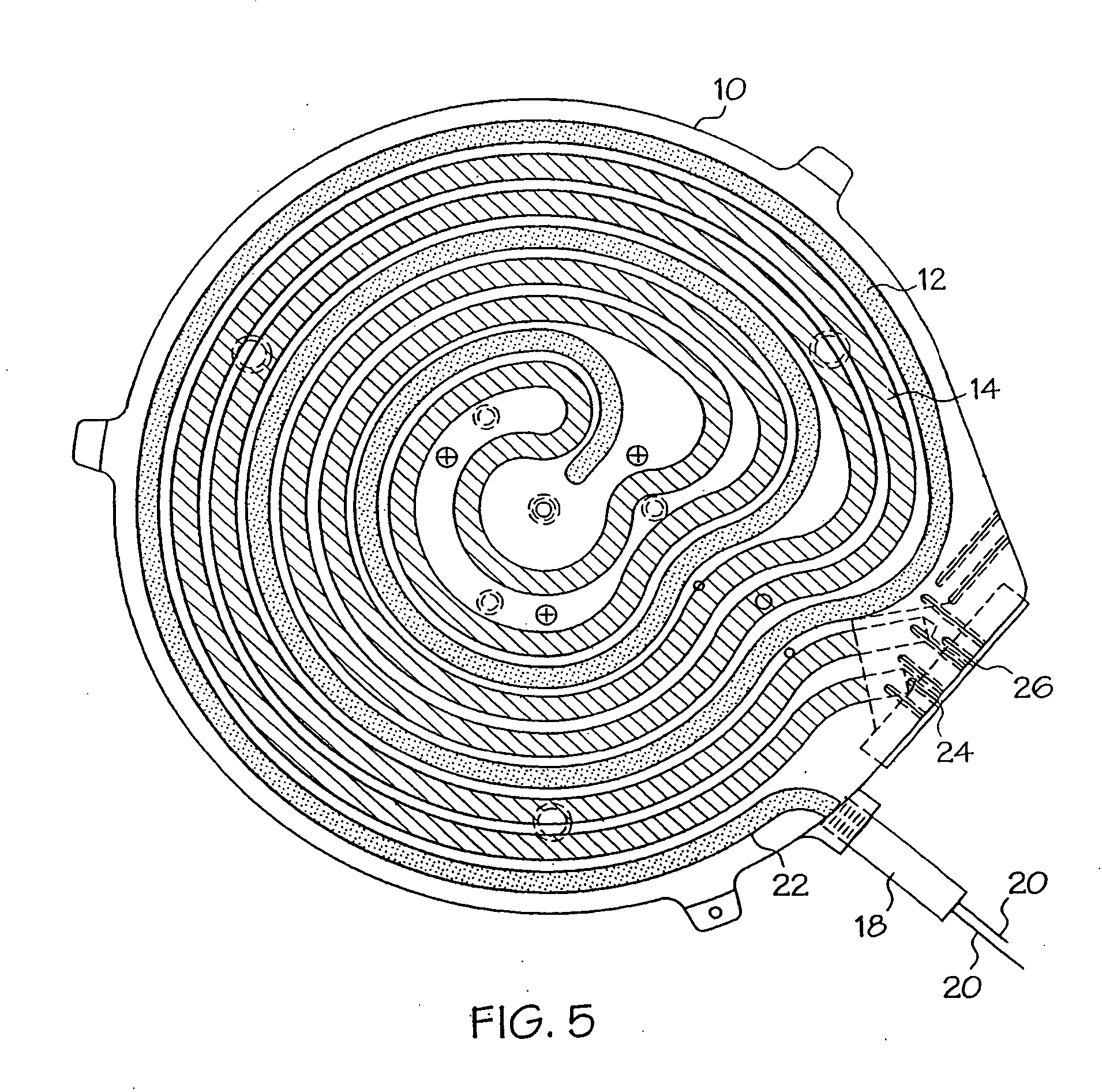
[0007] To facilitate locating both the heating element and the cooling element in the same plane in coiled configurations, the heating and cooling elements are spatially interleaved with each other. The interleaved nature of the heating and cooling elements also provides more uniform heating and cooling of the chuck and, therefore, more uniform temperature across the surface of the wafer. Also, warping and other distortion of the chuck over temperature are substantially eliminated, such that the chuck can hold the wafer extremely flat over temperature.
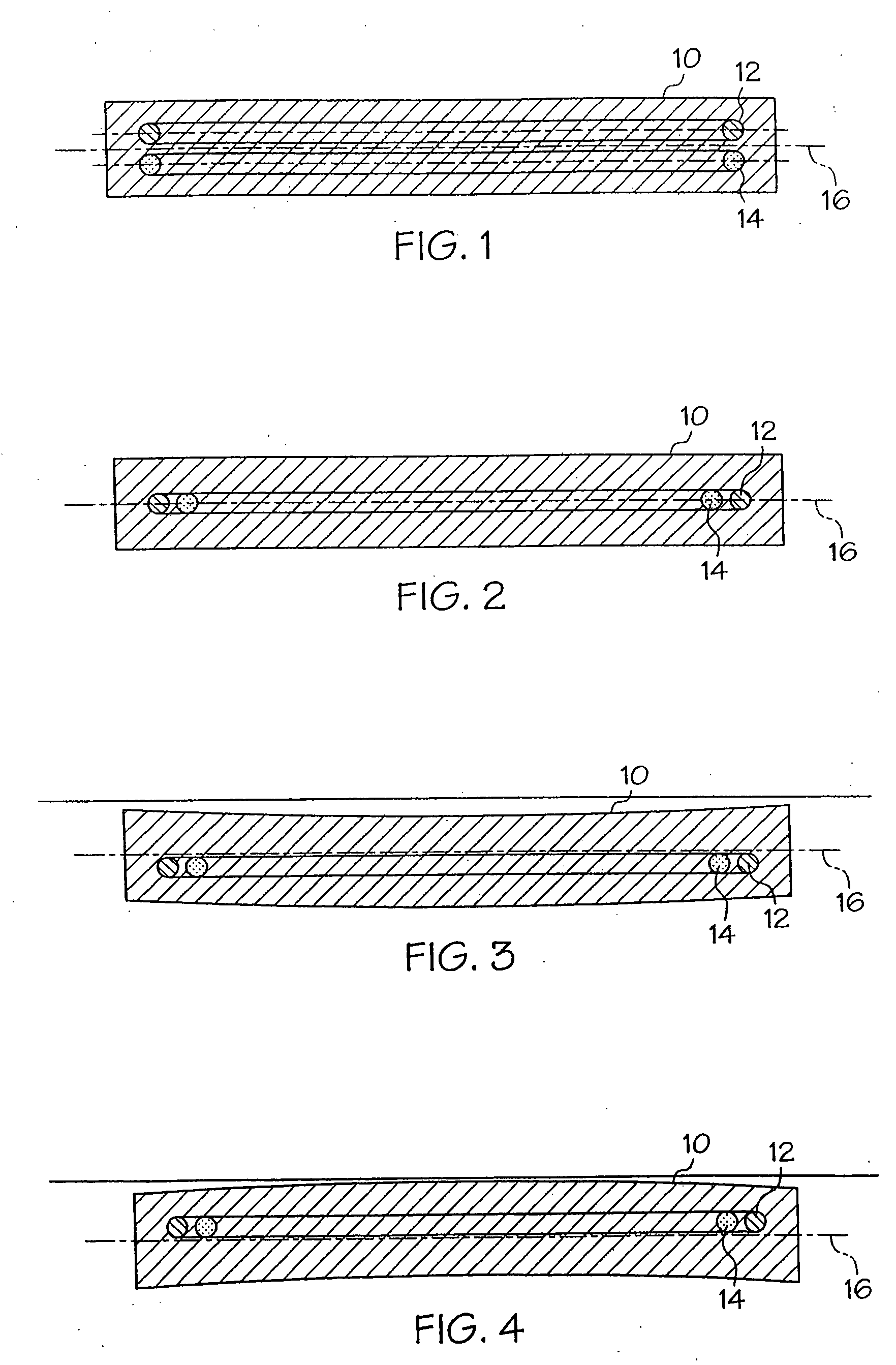
[0008] In one embodiment, warping and other distortions over temperature are further reduced by the selection of the location of the heating and cooling plane within the thermal plate assembly. In this embodiment, the heating and cooling planes are located in a center plane of the thermal plate assembly, i.e., the plane that is equidistant from the top and bottom surfaces of the thermal plate assembly. With the heating and cooling planes located at the vertical center of the thermal plate assembly, distortions caused by doming and / or dishing of the thermal plate assembly are substantially eliminated. Again, with the reduction in chuck distortion over temperature, the wafer can be held flat over temperature.
[0009] In one embodiment, the thermal plate assembly of the invention is made from a cast material, which, in one particular embodiment, is aluminum. The casting of the housing provides the thermal plate assembly with improved mechanical rigidity and stability over temperature. The housing casting can be stress relieved such as by heat treating at predetermined manufacturing steps. For example, stress relieving can be performed both before and after finish machining of the housing. The stress relief provides the housing with more mechanical stability over temperature. Also, the housing casting can be formed with the tubes for circulating the cooling fluid. With the stress relief procedure, even more mechanical stability is provided.
[0011] This configuration provides the chuck of the invention with flexibility according to the setting in which the chuck is being used. For example, one type of top surface assembly may be required where the test being performed requires the chuck to be able to absorb a large amount of power. In another test, the top surface assembly may be required to provide low electrical capacitance, high voltage or high electrical isolation performance. In still another test, the top surface assembly may be required to provide for very low signal leakage. In each of these tests, the top surface assembly may be fabricated differently to provide optimal performance under the specific testing parameters. In a conventional chuck system, this would require the user to obtain several different chucks, one for each test type. However, in accordance with this aspect of the invention, the thermal plate assembly of the invention provides a universal type mount which can accommodate all of the various top surface assemblies. As a result, the user need only have a single thermal plate assembly. The user can then purchase only the top surface assemblies required for the tests to be performed. This results in considerable cost savings to the user.
[0012] In another aspect, the invention is directed to an approach to eliminating the negative effects resulting from the relative movement of layers of the workpiece chuck over temperature. When two adjacent chuck layers have different thermal expansion coefficients, they tend to rub each other over temperature. This can cause abrasion of the surfaces which can degrade chuck performance. This is especially true in one particular example where a top surface assembly made of a hard abrasive ceramic material is located adjacent to the cast aluminum housing of the thermal plate assembly. To reduce these effects, one or more adjacent surfaces can be coated with a hard coating, such as hard anodize.

Problems solved by technology

This requirement is especially challenging in a temperature-control chuck where the chuck must maintain mechanical and electrical stability over a wide range of temperatures.
At temperature extremes, particularly at high temperatures, conventional wafer chucks tend to distort due to thermal expansion and contraction and the integrity of the materials of which the chucks are constructed.
For example, chucks made of softer materials will tend to distort at high temperature.
This problem is exacerbated by the increasing mechanical loads on the chuck introduced by the test system, i.e., the wafer prober.

Method used


Image

  • Wafer chuck having thermal plate with interleaved heating and cooling elements
  • Wafer chuck having thermal plate with interleaved heating and cooling elements
  • Wafer chuck having thermal plate with interleaved heating and cooling elements

Examples


Embodiment Construction

[0025] The present invention is directed to and is applicable in temperature-controlled workpiece chucks of the type described in, for example, U.S. Pat. No. 6,019,164, issued Feb. 1, 2000, entitled, “Workpiece Chuck,” assigned to Temptronic Corporation, and incorporated herein in its entirety by reference; U.S. Pat. No. 6,073,681, issued Jun. 13, 2000, entitled, “Workpiece Chuck,” assigned to Temptronic Corporation, and incorporated herein in its entirety by reference; and copending U.S. patent application Ser. No. 09 / 473,099, filed on Dec. 28, 1999, entitled, “Workpiece Chuck,” assigned to Temptronic Corporation, and incorporated herein in its entirety by reference.

[0026] These chucks include a heater for heating the wafer under test and a heat sink for removing heat to cool the wafer. In accordance with the present invention, the heater and heat sink are formed in one integral assembly referred to herein as a thermal plate or thermal plate assembly. In one embodiment, the housin...


PUM

PropertyMeasurementUnit
isolation impedanceaaaaaaaaaa
thermal distortionaaaaaaaaaa
temperatureaaaaaaaaaa

Abstract

A workpiece chuck includes a thermal plate assembly which includes both heating and cooling capability. The heating element can be a resistive heater in a coiled configuration disposed in a plane. The cooling can be performed via a cooling fluid circulated through cooling tubes which are also disposed in a coiled configuration in a plane. The plane of the heating element and the cooling tubes can be the same plane, and that plane can be a center plane of the thermal plate assembly. By locating the heating and cooling in the same plane, uniform heating and cooling are achieved. Also, by locating the heating element and cooling tubes in the center of the thermal plate, distortions such as doming and dishing in the thermal plate are eliminated such that the wafer can be held extremely flat on the chuck. The heating element and cooling tubes are coiled in an interleaved fashion to provide uniform heating and cooling while allowing them to simultaneously occupy the same plane.

Description

RELATED APPLICATIONS [0001] This application is a continuation of U.S. patent application Ser. No. 10 / 465,716, filed Jun. 19, 2003, which is a continuation of U.S. patent application Ser. No. 09 / 900,285, filed Jul. 6, 2001, now U.S. Pat. No. 6,700,099, which is based on U.S. Provisional Patent Application Ser. No. 60 / 217,036, filed on Jul. 10, 2000. The contents of all of these applications and patent are incorporated herein in their entirety by reference.BACKGROUND OF THE INVENTION [0002] A workpiece chuck can be used to hold workpieces such as semiconductor wafers during processing and testing. Because integrated circuits formed in a wafer under test are commonly tested over temperature, the workpiece chuck can include a temperature control system for controlling the temperature of the wafer during testing. As integrated circuits become smaller and more densely integrated, positioning tolerances for testing systems such as wafer probers decrease. With very small positioning tolera...

Claims


Application Information

Patent Timeline
Patent Type & Authority Applications(United States)
IPC IPC(8): C23C16/00H05B3/18G01R31/28H01L21/00H01L21/02H01L21/66H01L21/683H01L21/687H05B3/70
CPCG01R31/2891H01L21/68785H01L21/67109H01L21/67103
Inventor COLE, KENNETH M. SR.STONE, WILLIAM M.OLSEN, DOUGLAS S.
Owner TEMPTRONIC
Why Eureka
Eureka Blog
Learn More