Burner ignition controller

Active Publication Date: 2008-11-27
R W BECKETT
View PDF18 Cites 4 Cited by
  • Summary
  • Abstract
  • Description
  • Claims
  • Application Information

AI Technical Summary

Benefits of technology

[0009]The invention is directed to a fuel burner controller and related methods that is operable to provide various control signals to establish combustion upon a call for heat. In the event that a loss of flame is detected during a call for heat, the controller initiates a recycle procedure in

Problems solved by technology

If successful ignition and continued combustion cannot be established prior to the depletion of the timing budget during the uninte

Method used


Image

  • Burner ignition controller
  • Burner ignition controller
  • Burner ignition controller

Examples


Embodiment Construction

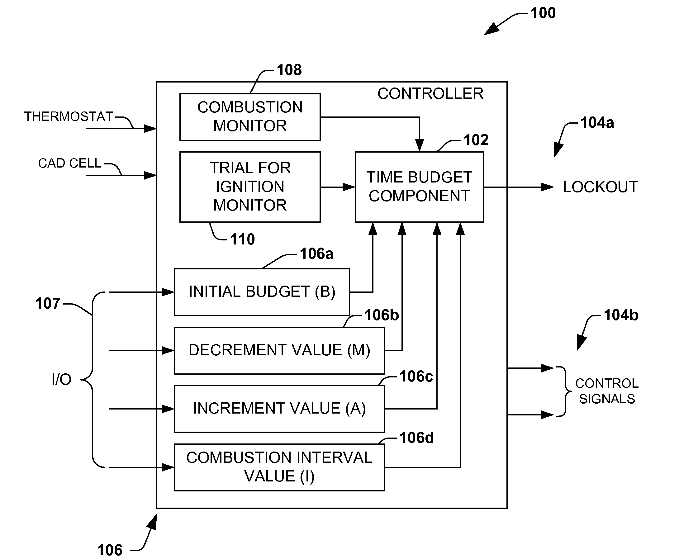
[0018]The present invention will now be described with reference to the attached drawings, wherein like reference numerals are used to refer to like elements throughout. The invention is directed to a fuel burner controller that is operable to provide various control signals to establish combustion upon a call for heat. In the event that a loss of flame is detected during a call for heat, the controller initiates a recycle procedure in which an attempt to re-establish combustion is performed. The controller employs a time budget management system that attempts to minimize the amount of time the fuel burner is permitted to attempt to establish combustion in circumstances where the burner is unable to properly sustain a flame.

[0019]In one embodiment of the invention, when an initial call for heat is provided by the thermostat, an initial time budget for achieving ignition is established or otherwise provided. If successful ignition and continued combustion cannot be established prior ...


PUM


Abstract

A fuel burner controller and associated method is configured to establish fuel combustion in a fuel burner and to recycle a fuel combustion initiation process when a loss of combustion is detected and a call for heat is asserted. The controller is further configured to limit a number of recycles of the fuel combustion initiation process based on a time budget.

Description

REFERENCE TO RELATED APPLICATION[0001]This application claims priority to and the benefit of U.S. Provisional Application Ser. No. 60 / 939,557 which was filed May 22, 2007, entitled BURNER IGNITION CONTROLLER, the entirety of which is hereby incorporated by reference as if fully set forth herein.FIELD OF INVENTION[0002]The present invention relates generally to a fuel burner controller that employs a time budget system to limit an amount a fuel burner will recycle under particular fuel burner conditions.BACKGROUND OF THE INVENTION[0003]Fuel burner systems for use in furnaces, boilers, water heaters etc. are well known in the prior art. One type of fuel burner is an oil burner, and is employed in various types of apparatus, such as boilers, furnaces, water heaters, etc. In such applications, an oil burner receives a fuel oil and initiates combustion thereof to generate heat which is then employed in various manners to perform work. Although several types of oil burners exist, one exem...

Claims


Application Information

Patent Timeline
IPC IPC(8): F23N5/20
CPCF23N5/203F23N2027/02F23N2227/02
Inventor BOHAN, JR., JOHN E.
Owner R W BECKETT
Why Eureka
Try Eureka