Try-in implant with handle

a technology of implant and handle, which is applied in the field of tryin implants, can solve the problems of surgeons without visual impressions and difficult handling, and achieve the effect of maximum strength

Inactive Publication Date: 2008-11-27
STRAUMANN HLDG AG
View PDF16 Cites 18 Cited by
  • Summary
  • Abstract
  • Description
  • Claims
  • Application Information

AI Technical Summary

Benefits of technology

[0021]Typically, a series of x-rays are taken in order to determine where and how to position the implants in the jaw bone without damaging surrounding structures such as the nerves in the lower jaw bone and the sinuses adjacent to the upper jaw bone. Based on said x-ray the pilot hole is drilled in the jaw bone. If, according to a further embodiment of the present invention, the try-in implant is made of a metal or synthetic material, which is X-ray visible, a further x-ray can be taken to determine the angulation of the pilot hole relative to existing dentition and the depth of the pilot hole relative to anatomical restriction. A possible synthetic material, which is X-ray visible, is BaSO4 containi

Problems solved by technology

However, the devices known up to now have the disadvantage that the surgeon has no visual impression which indicat

Method used


Image

  • Try-in implant with handle
  • Try-in implant with handle
  • Try-in implant with handle

Examples


Embodiment Construction

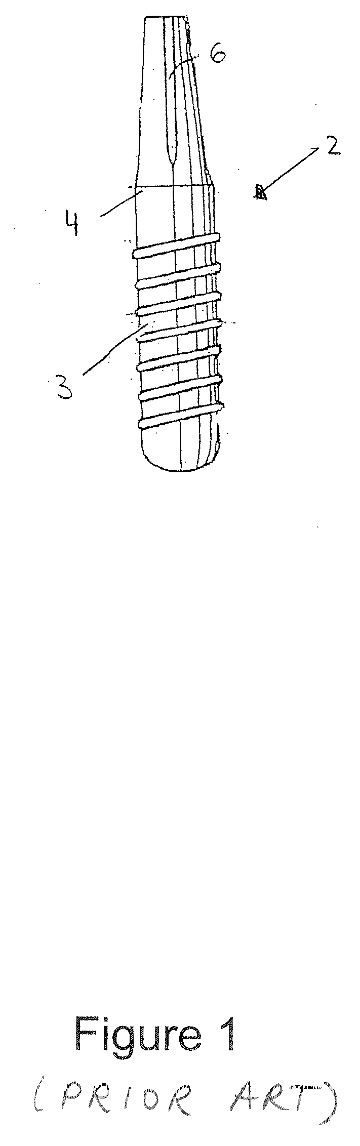
[0031]FIG. 1 shows one embodiment of a final implant in the form of a one-part implant 2 according to the state of the art. It comprises an anchoring part 3 with a threaded section, a neck part 4 and a mounting part 6.

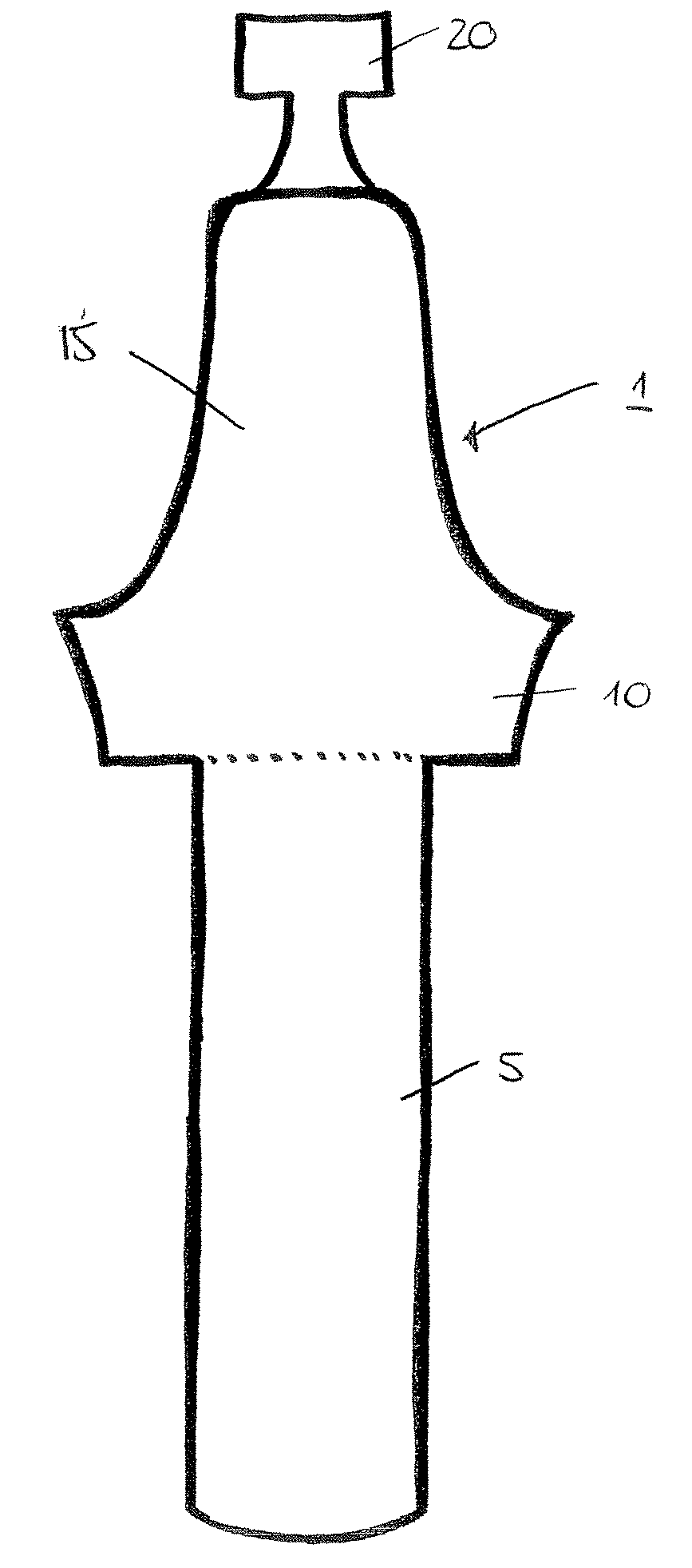
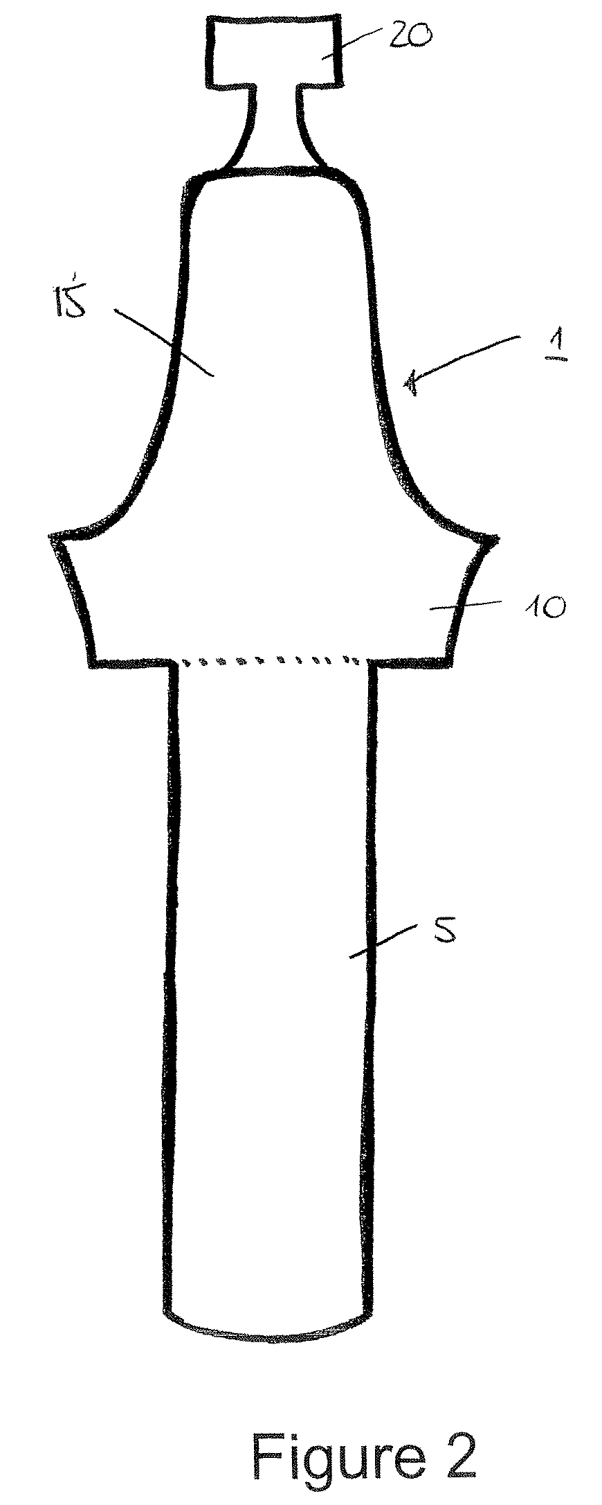
[0032]FIG. 2 shows a try-in implant 1 according to one embodiment of the present invention. The try-in implant 1 comprises a body portion 5 to be received in a pilot hole. The body portion 5 has a length of about 6 to 8 mm and corresponds to the drill hole and subsequently the anchoring part 3 of the final implant. At the upper end of the body portion 5 a neck portion 10 having a length of about 1 mm is formed which may comprise a slightly enlarged conical section. Above said neck portion 10 an attachment portion 15 having a length of about 1 to 6 mm is formed, which corresponds to the mounting part 6 of the final implant. The attachment portion 15 includes a handle 20 which ensures easy and safe handling of said try-in implant 1. The handle may have various forms, whi...


PUM


Abstract

A try-in implant for verifying the position and angulation of a pilot hole and thereby providing a visual impression of the final implant position. The try-in implant comprises a body portion to be received in the pilot hole, a neck portion formed above the body portion, and an attachment portion formed above the neck portion. The attachment portion includes a handle to ensure easy and safe handling of the try-in implant.

Description

FIELD OF THE INVENTION[0001]The present invention relates to a try-in implant for verifying the position and angulation of a pilot hole.BACKGROUND[0002]When installing dental implants, the positioning of the implant is extremely important to obtain a good aesthetic and functional result. The positioning of the implant to a large extent determines the choice of prosthetic components. In order to provide guidance for the surgeon during the installation of an implant, various types of so-called surgical guide rails have traditionally been used. These guide rails are mainly produced under laboratory conditions and can be made in a number of different designs. As aids during the surgical intervention it is also possible to use so-called directional sensors.[0003]U.S. Pat. No. 5,208,845 discloses a radiographic depth gauge for positioning dental implants in a jaw bone. The gauge is formed of a material, which is x-ray visible, and is an elongated member with distance markings. The gauge b...

Claims


Application Information

Patent Timeline
IPC IPC(8): A61C13/36
CPCA61C1/084A61C8/0089
Inventor LUSSI, JOSTLAZIC, MIODRAG
Owner STRAUMANN HLDG AG
Why Eureka
Try Eureka