Connector and electrical connection device

a technology of connecting rods and connectors, applied in the direction of coupling devices, electrical devices, connections, etc., can solve the problems of unreliable connection, and achieve the effects of preventing deformation of fitting elements, simple device construction, and easy releas

Active Publication Date: 2008-11-27
JST MFG CO LTD
View PDF5 Cites 12 Cited by
  • Summary
  • Abstract
  • Description
  • Claims
  • Application Information

AI Technical Summary

Benefits of technology

[0022]In the connector of the present invention, it is also allowed that the plug element has a pair of terminal protectors formed into cylindrical shapes surrounding the peripheries of the pair of fitted elements, the short-circuiting element has a pair of outer peripheral walls formed into cylindrical shapes into which the pair of terminal protectors are inserted and which surround the peripheries of the pair of fitting elements, and on each of the pair of outer peripheral walls, an end portion of the outer peripheral wall and the latch receiving portion are arranged along the inserting direction in order from the side of the plug element, and in the state where the plug element is inserted into the socket element, when the latching element at the first latching position is pushed, by contact between each of the tip ends of the pair of first legs and each of the end portions of the pair of outer peripheral walls, the pair of first legs elastically bend to the radially outer sides of the outer peripheral walls, and the latching convex portion comes apart from the position of the latch receiving convex portion and the contact surface and the contacted surface are separated from each other, so that the latching at the first latching position is released, and as a result, the latching element becomes movable to the second latching position. Accordingly, deformation of the fitting elements can be prevented, and latching can be easily released by a simple device construction. In addition, a device construction in which the latching element is latched on the plug element can be simply and reliably realized. Further, in conjunction with pushing of the latching element, the plug element is reliably inserted into the socket element. The operation for connecting both components and the operation for pushing the latching element in for removing a short circuit of the short-circuiting piece can be m...

Problems solved by technology

In addition, the shape of the socket element differs depending on its type, so that the latching element must be designed and manufactured for each socket element type to realize reliable connection of the connection device, and this is ...

Method used


Image

  • Connector and electrical connection device
  • Connector and electrical connection device
  • Connector and electrical connection device

Examples


Embodiment Construction

[0045]Hereinafter, a preferred embodiment of the present invention will be described with reference to the drawings.

(Entire Construction)

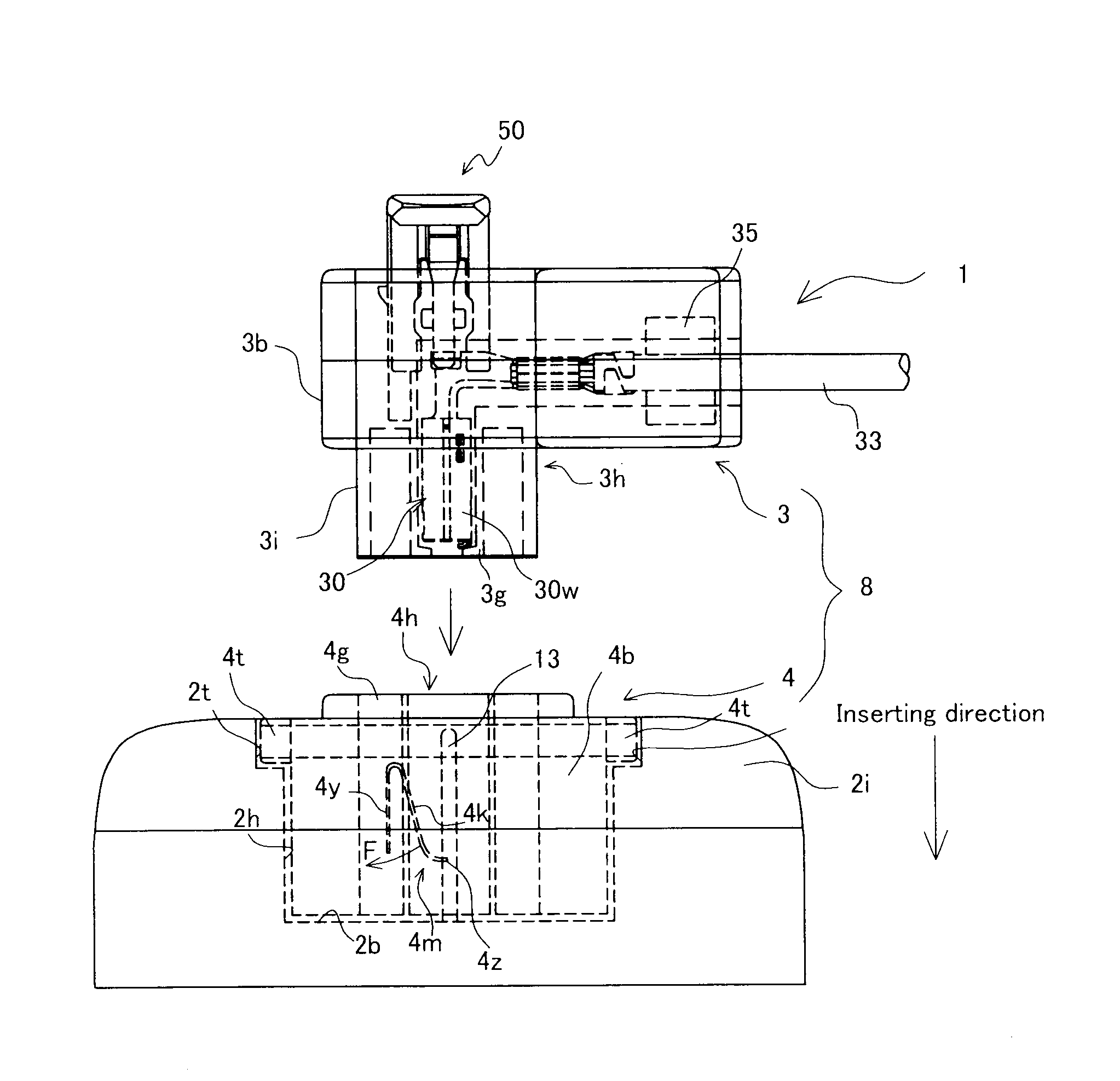
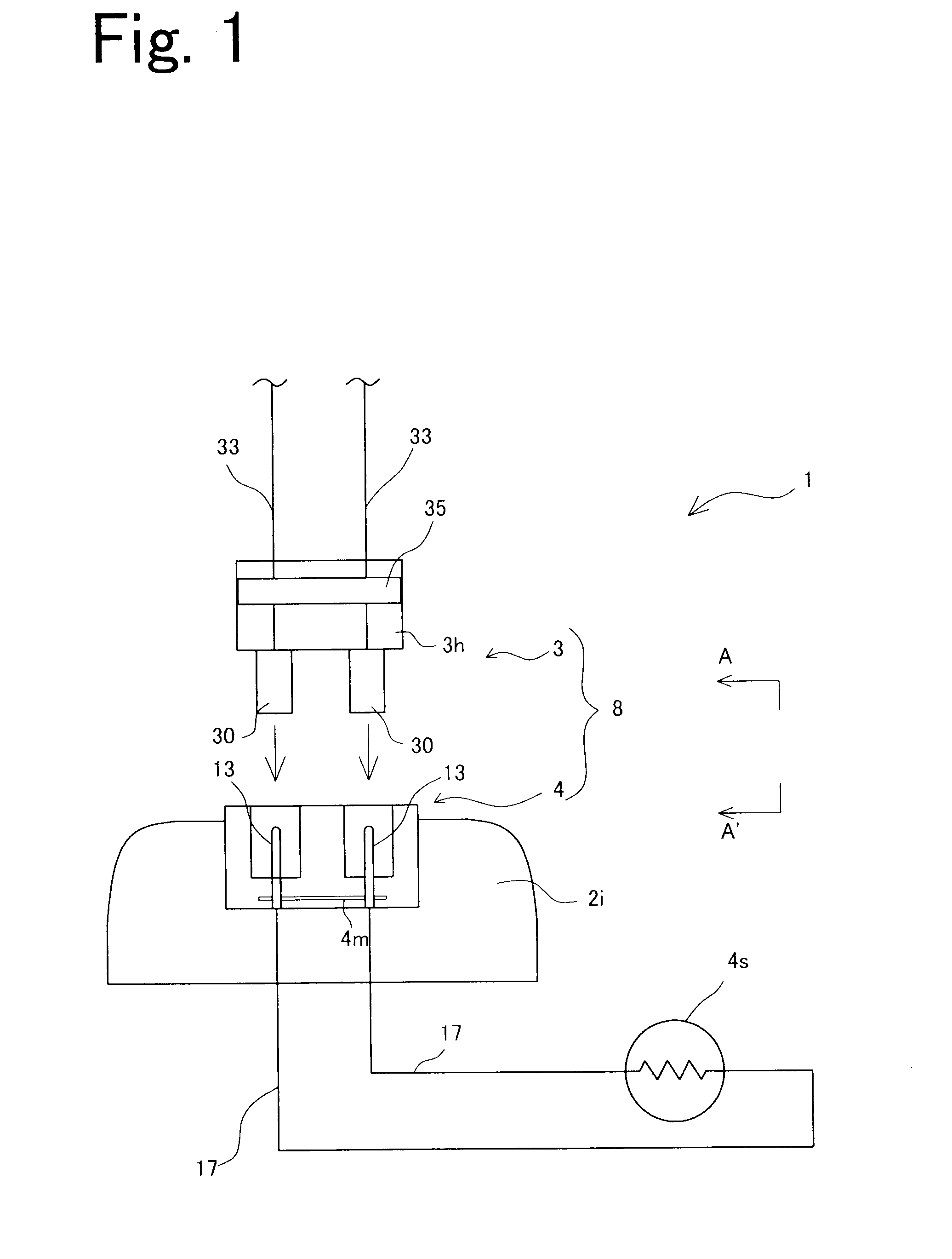
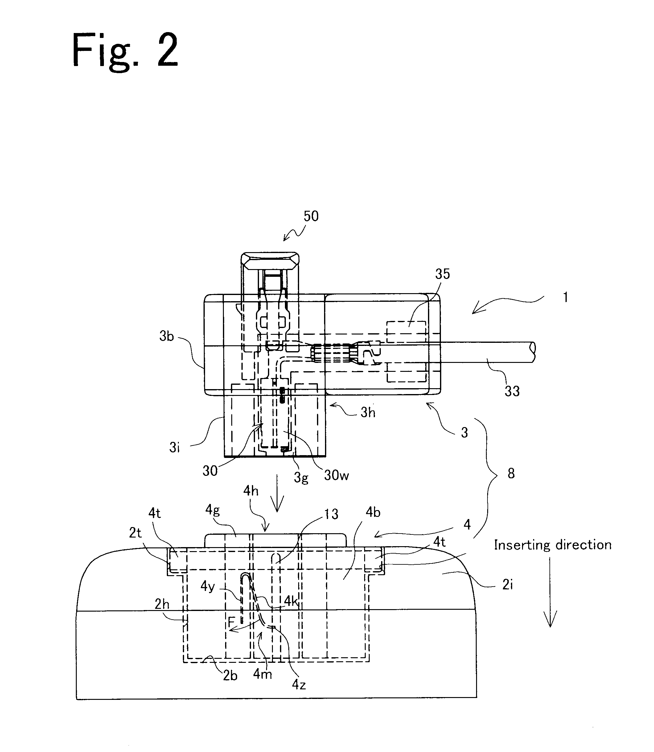
[0046]First, the entire construction of the electrical connection device of an embodiment of the present invention will be described with reference to FIG. 1. FIG. 1 is a schematic view of the electrical connection device relating to this embodiment.

[0047]As shown in FIG. 1, the electrical connection device 1 includes a socket element 2i and a connector 8. In this embodiment, the socket element 2i is a housing of an airbag inflator, and supports a pair of pins (fitting elements) 13. The connector 8 includes a plug element 3, a short-circuiting element 4, and a latching element 50, and is connected to a socket element 2i supporting the pair of pins 13. The plug element 3 supports a pair of female terminals (fitted elements) to be electrically connected to the pair of pins 13, and is inserted into the socket element 2i and engages with the socket ele...


PUM


Abstract

A connector 8 includes a plug element 3, a short-circuiting element 4, and a latching element 50 to be latched at a first latching position and a second latching position. When the latching element 50 is at the second latching position, a short-circuiting piece 4m moves to a non-short-circuit position. The latching element 50 has latch portions 52 formed in a projecting manner, and the short-circuiting element 4 has latch receiving portions 41a. In a state where the plug element 3 is inserted into the socket element 2i, when the latching element 50 is at the second latching position, the latch portions 52 and the latch receiving portions 41a engage with each other to prevent separation between the socket element 2i and the plug element 3.

Description

BACKGROUND OF THE INVENTION[0001]1. Field of the Invention[0002]The present invention relates to a technical field of an electrical connection device, and specifically, to a connector and an electrical connection device including a latching element provided in a plug element, constructed so that, when a socket element and the plug element are not properly connected, electric contacts of the socket element are short-circuited by each other, and when these elements are properly connected, the short-circuited state between the electric contacts is removed.[0003]The present invention is suitable especially to be for being applied to an airbag system. Hereinafter, application to the airbag system will be described mainly, however, the present invention is also applicable to a wide variety of uses and environments.[0004]2. Description of Related Art[0005]An airbag system includes an airbag assembly attached to a section that cannot be observed from the outside of a driver's cabin of a veh...

Claims


Application Information

Patent Timeline
IPC IPC(8): H01R13/70
CPCH01R13/6273H01R2201/26H01R13/7032H01R13/639
Inventor OSADA, TSUYOSHIYAGI, TAKAMASA
Owner JST MFG CO LTD
Why Eureka
Try Eureka