Bone Anchor With Locking Cap and Method of Spinal Fixation

a technology of bone anchors and locking caps, applied in the field of bone anchors, can solve problems such as not providing a force on the body, and achieve the effect of shortening the clamping process

Active Publication Date: 2008-11-27
DEPUY SYNTHES PROD INC
View PDF56 Cites 228 Cited by
  • Summary
  • Abstract
  • Description
  • Claims
  • Application Information

AI Technical Summary

Benefits of technology

[0007]The locking cap advantageously simplifies and preferably shortens the clamping process. The locking cap preferably includes a main body, a set screw, and a saddle. The set screw is preferably preloaded into the main body so that upon application of a torque, preferably below a predetermined amount, for example about 4.5 Newton-meters, the main body rotates with the set screw. Preferably, the saddle is in contact with or coupled to the set screw. Typically, after the anchor member is implanted into a bone and a rod is inserted into the bone anchor, the locking cap is positioned on top of the anchor head where features of the main body engage features of the head to allow the locking cap preferably to lock into place on the anchor head preferably with about a 90° turn or less. The instrument preferably engages the set screw and application of a rotary motion in a direction to lock the cap to the body (anchor head) also rotates the main body so that the main body is coupled to the bone anchor. Once the rod and anchor member are aligned as desired, the set screw can then be twisted into the anchor head, which causes the saddle to engage and then clamp the rod in place. As a result, the clamping of the rod may cause the anchor member in a polyaxial bone anchor to be clamped in place. Alternatively the anchor member may be locked to the anchor head in a polyaxial bone anchor independently of the rod to be clamped to the bone anchor. Advantageously, features of the main body and set screw allow the same tool to be used in a single action to position and lock the main body into the anchor head and to then rotate the set screw.

Problems solved by technology

As a result, the clamping of the rod may cause the anchor member in a polyaxial bone anchor to be clamped in place.
When the main body attaches to the body, the dovetail projections are received in the dovetail grooves to prevent splaying but the dovetail connection in some embodiments may not provide a force on the body during rotation of the main body.

Method used


Image

  • Bone Anchor With Locking Cap and Method of Spinal Fixation
  • Bone Anchor With Locking Cap and Method of Spinal Fixation
  • Bone Anchor With Locking Cap and Method of Spinal Fixation

Examples


Embodiment Construction

[0036]While the bone anchor will be illustrated and described herein with reference to certain preferred or exemplary embodiments, the invention should not be limited to these preferred or exemplary embodiments. Furthermore, the features described and illustrated herein can be used singularly or in combination with other features and embodiments.

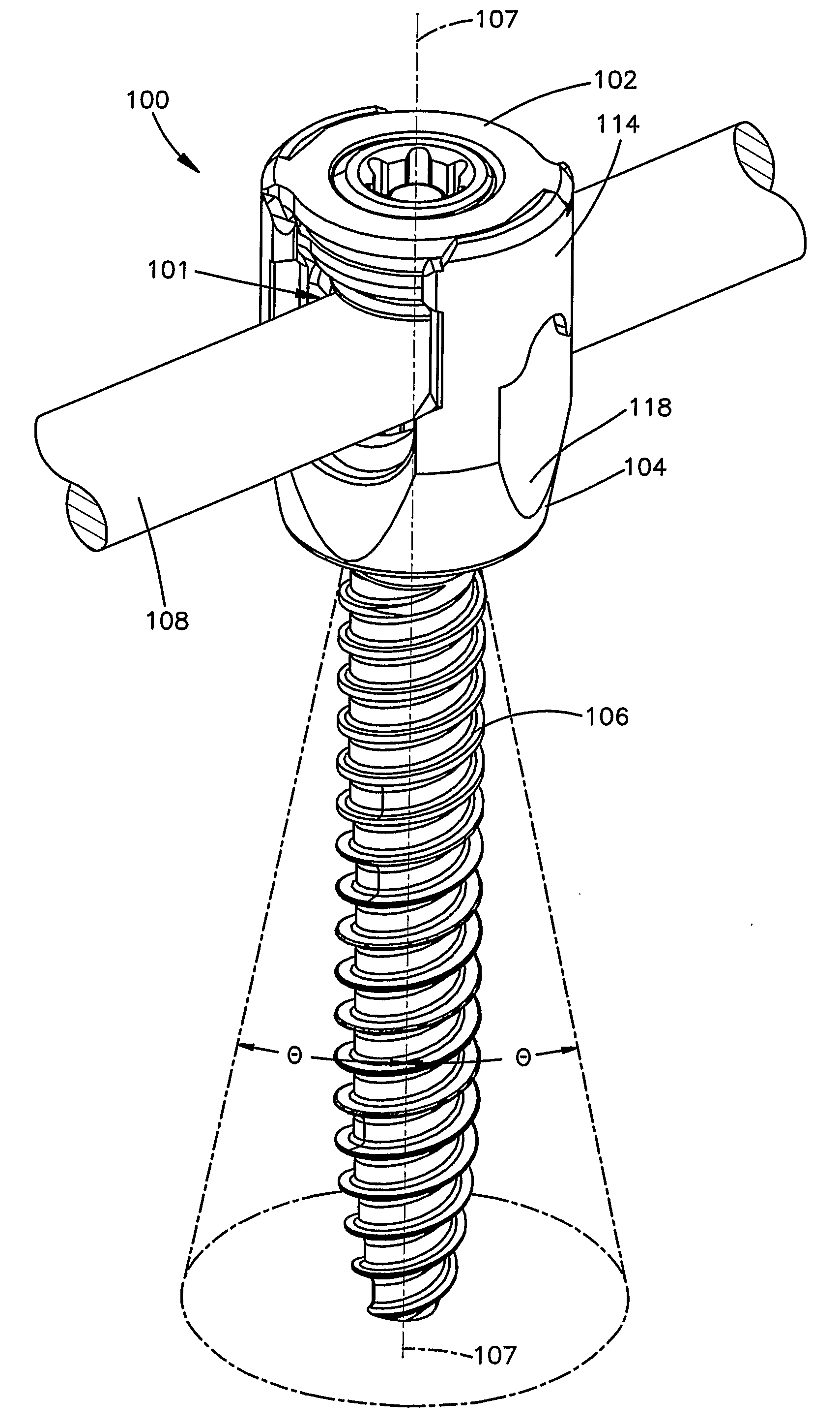
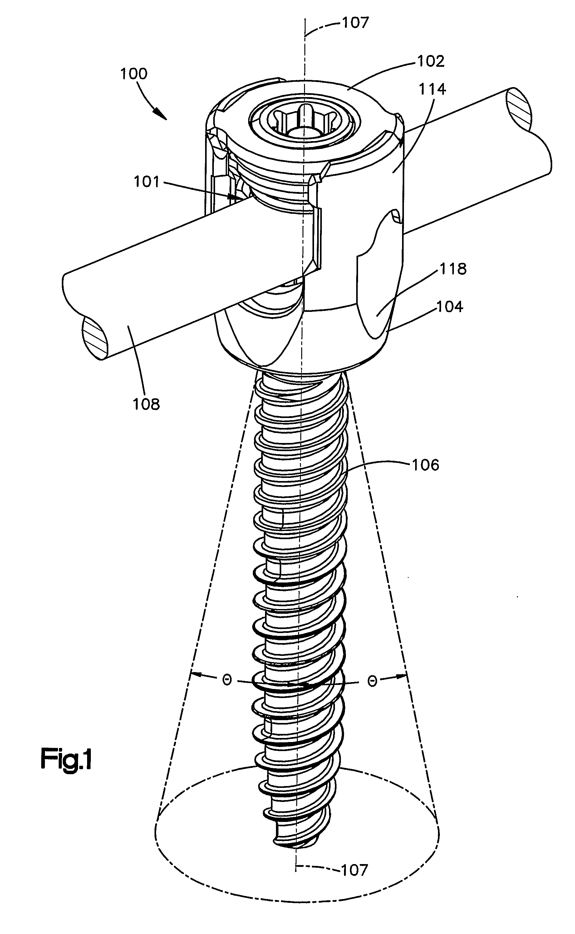
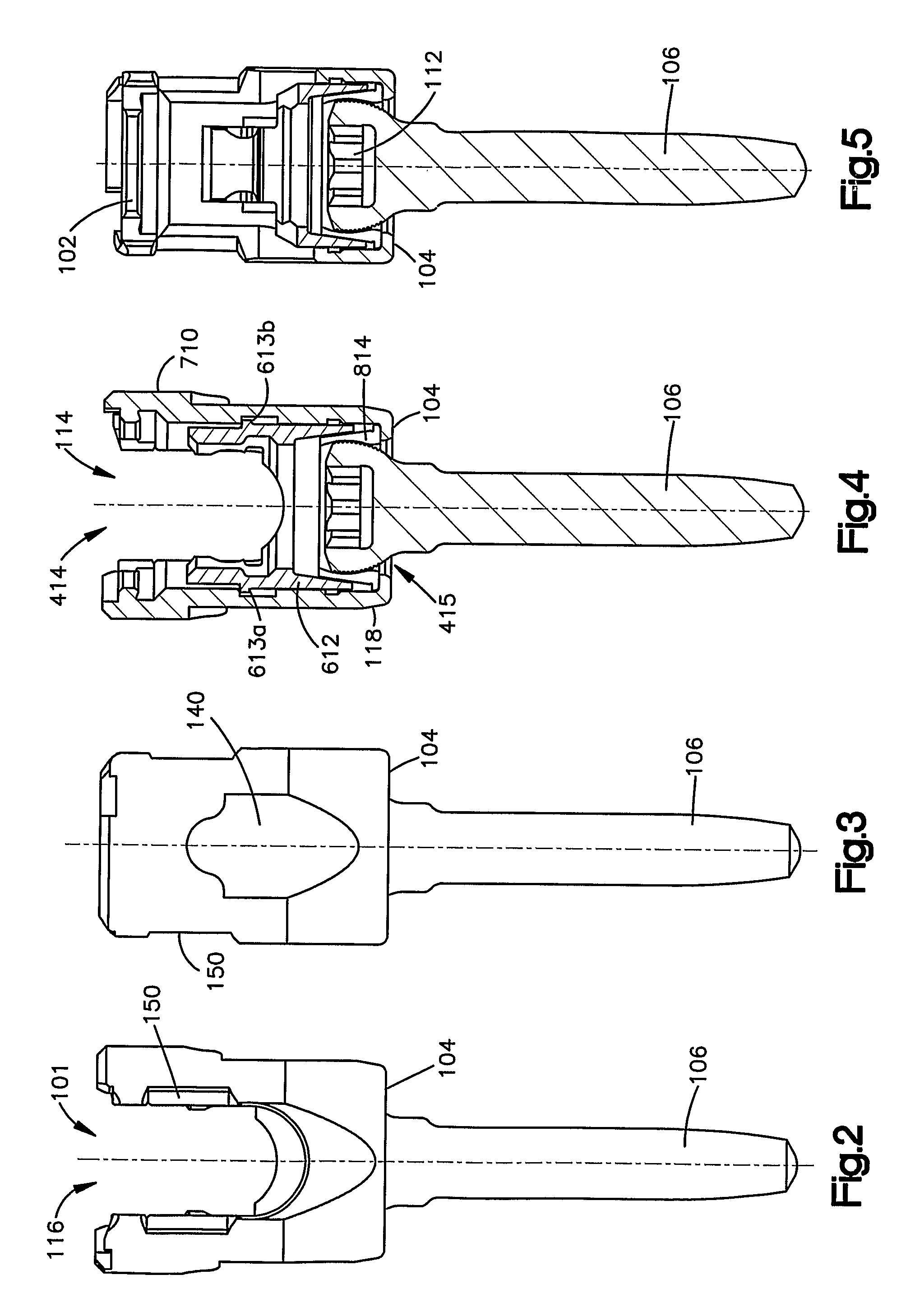
[0037]FIGS. 1-6 show an embodiment of a polyaxial bone anchor. Polyaxial bone anchor 100 includes a locking cap 102 (not shown in FIGS. 2-5), an anchor head 104, and an anchor member 106. Bone anchor 100 may also be a monoaxial bone anchor such that the anchor member and anchor head are integral members that are fixed together. (See FIG. 39). Anchor head 104 (sometimes referred to in the art as the body) has a generally U-shaped opening 101 for receiving a spinal rod 108 (note that spinal rod 108 is not shown in FIGS. 2-6) or other device, such as, for example, a plate. Anchor member 106, which may be a bone screw, hook, or other similar str...


PUM


Abstract

A bone anchor (100) for attaching a rod (108) to a bone has an anchor member (106) for attachment to the bone and an anchor head (104) having a U-shaped opening for receiving the rod. The bone anchor also includes a locking cap (102) that has a main body (900) and a set screw (1000). Advantageously, in one embodiment the locking cap preferably is designed such that a single tool can be used to lock the locking cap in place on the anchor body preferably with a 90° turn and preferably then drive the set screw to clamp the rod. The locking cap also preferably non-threadingly engages the anchor body. The anchor body preferably has an inclined surface on its top surface which elastically deflects extending tabs on the main body to secure the locking cap to the anchor body. A method of implantation and assembly of the bone anchor are also described.

Description

TECHNICAL FIELD OF THE INVENTION[0001]This invention relates to bone fixation devices and related methods of fixation. More specifically, this invention relates to bone anchors, such as screws and hooks for spinal fixation including polyaxial bone anchors, and related methods of spinal fixation.BACKGROUND OF THE INVENTION[0002]Many methods of treating spinal disorders are known in the art. One known method involves anchoring a screw or a hook to the vertebrae, and fixing the screws or hooks along a spinal rod to position or immobilize the vertebrae with respect to one another. The screws or hooks commonly have heads with U-shaped channels in which the spinal rod is inserted and subsequently clamped by a set screw or other fastener or locking cap. This method may commonly involve multiple screws or hooks, as well as multiple spinal rods. With this method, the spinal rod(s) may be shaped to maintain the vertebrae in such an orientation as to correct the spinal disorder at hand (e.g., ...

Claims


Application Information

Patent Timeline
Patent Type & Authority Applications(United States)
IPC IPC(8): A61B17/04
CPCA61B17/7032A61B17/8605A61B17/7037A61B17/56A61B17/58A61B17/70A61B2017/567A61B2017/681
Inventor PETERSON, JOSEPHCHIEN, DENNISKEYER, THOMASMCSHANE, EDWARDCAPOZZOLI, JOSEPHHAURI, PASCALKRAMER, SCOTTBOCKHORST, SANDRASCHINDLER, DAVID
Owner DEPUY SYNTHES PROD INC
Why Eureka
Try Eureka