A process and device for integrated chip blowing and dehydration

A dehydration device and process technology, which are applied in the directions of cleaning methods, chemical instruments and methods, cleaning methods and utensils using gas flow, etc., can solve the problems of low efficiency of cleaning methods, difficulty in removing holes, and no cleaning, etc., and achieve economical savings. The effect of labor resources and site resources, reduction of handling and clamping procedures, and labor intensity reduction

Active Publication Date: 2016-08-24
GUANGDONG HONGTU TECHNOLOGY (HOLDINGS) CO LTD
View PDF6 Cites 0 Cited by
  • Summary
  • Abstract
  • Description
  • Claims
  • Application Information

AI Technical Summary

Problems solved by technology

When there are too many positions on the parts that need to be cleaned of chips, the efficiency of the traditional cleaning method is very low, the labor intensity of the workers is high, and the working environment is harsh. It is very easy to cause the risk of missing some positions due to employee fatigue.
[0004] In addition, the chips in the threaded holes, especially the threaded blind holes, are easily stuck in the threaded holes under the action of cutting fluid, and it is difficult to get out of the hole even if the high-pressure air gun blows continuously for a long time. Therefore, the chip cleaning effect of the product is excellent. Stability is not guaranteed
[0005] Some parts have to be transported to the dehydration device for dehydration after chip blowing, and a dehydration process post and device need to be added. When producing similar products that do not need to be dehydrated, the device and site become idle, resulting in waste

Method used


Image

  • A process and device for integrated chip blowing and dehydration
  • A process and device for integrated chip blowing and dehydration
  • A process and device for integrated chip blowing and dehydration

Examples


Embodiment Construction

[0053] In order to make the object, technical solution and advantages of the present invention clearer, the present invention will be further described in detail below in conjunction with the accompanying drawings and embodiments. It should be understood that the specific embodiments described here are only used to explain the present invention, not to limit the present invention. The technical features involved in the various embodiments of the present invention described below may be combined with each other as long as they do not constitute conflicts with each other.

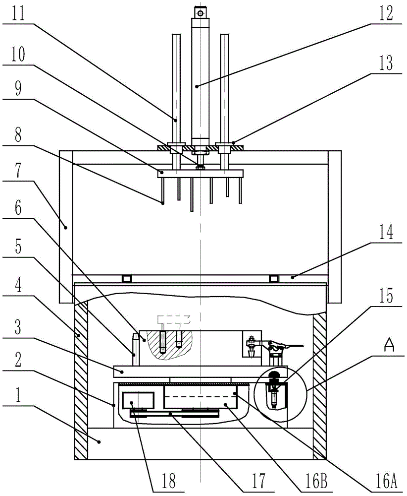
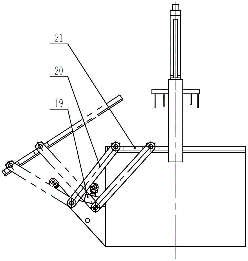
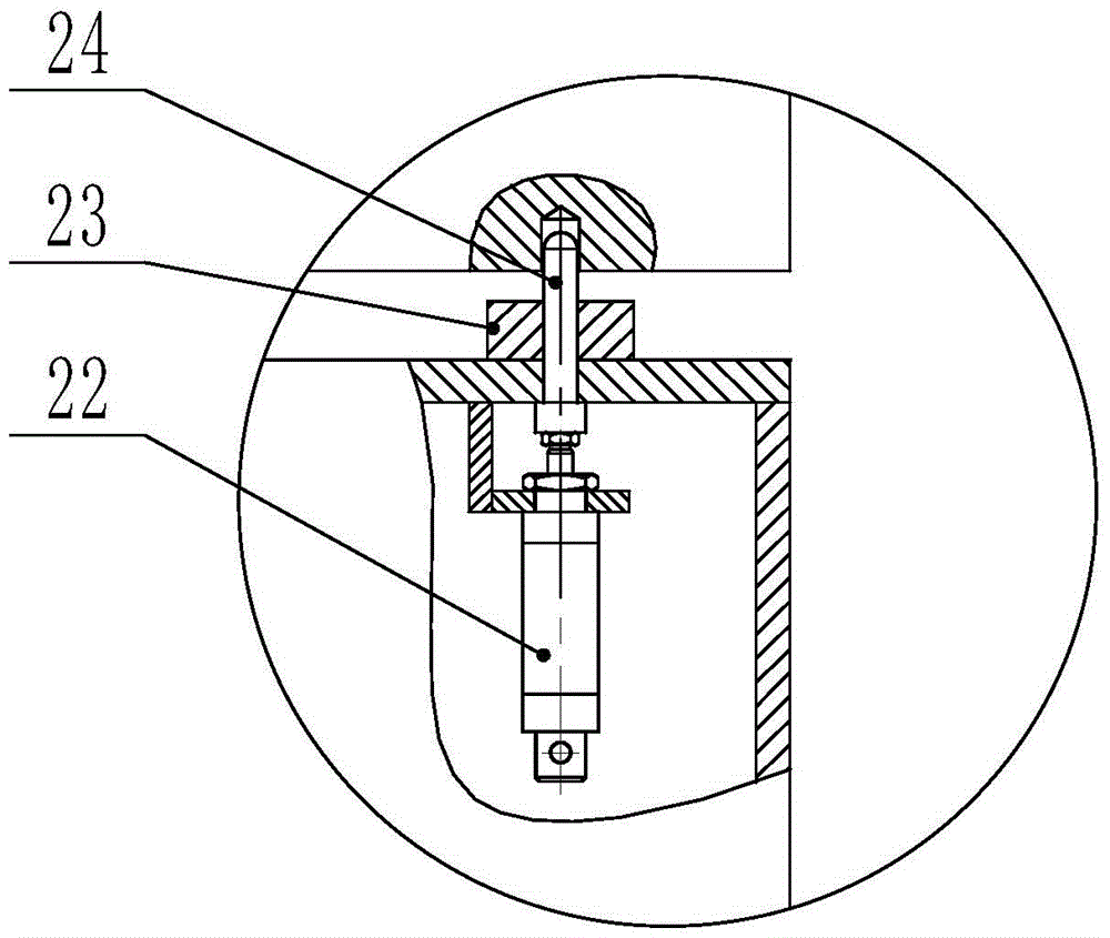
[0054] see Figure 1-Figure 3 , The device of the present invention includes a base 1 , a rotary device 2 , a clamp assembly 3 , an air blow assembly 10 , a protective drum 4 , a protective cover assembly 14 and a limit assembly 15 .

[0055]The swing device 2 includes a clutch 16B, a brake 16A, a belt 17 and a motor 18 . The motor 18 can drive the rotary device 2 to rotate through the belt 17 under the act...


PUM


Abstract

The invention discloses an integrated chip blowing-dewatering device which comprises a dewatering assembly, a chip blowing assembly and a protective cover assembly, wherein the dewatering assembly is received in a protective cylinder and dewatering treatment on parts on the dewatering assembly can be realized through the rotation of the dewatering assembly; the chip blowing assembly is mounted on a mounting rack which is arranged at the upper end of the protective cylinder, and capable of pushing an air blow pipe to extend into the protective cylinder for blowing air and to exit after chip blowing is completed; the protective cover assembly is used for covering the protective cylinder after the chip blowing assembly exits out of the protective cylinder so that the dewatering treatment can be carried out in the sealed protective cylinder by the dewatering assembly. The invention also discloses a method of integrated dewatering and chip blowing by using the device. The chip blowing action is automatically conducted by the chip blowing device, so that the labor intensity of the staff is greatly reduced; in the meantime, the chip blowing process of combined multiple intermittent chip blowing and continuous chip blowing is adopted so that the chip clearing effect is more ideal; in addition, chip blowing and dewatering are switched automatically, and the steps of carrying and clamping are reduced.

Description

technical field [0001] The invention relates to the technical field of cutting and cleaning in mechanical processing, in particular to an integrated process and device for chip cleaning and dehydration of parts, which is suitable for the integration of porous and complex machined parts such as automobile engine parts and automobile transmission system housings. Chemical blowing and dehydration. technical background [0002] The lightweight development trend of automobiles puts forward high integration, high performance and lightweight requirements for the design and manufacture of auto parts. It is applied to aluminum alloy die-casting parts such as automobile engine and automobile transmission system housing. In order to achieve this purpose, many solenoid valve holes, oil passage holes, sensor holes, threaded holes, etc. are integrated on one part. For such a complex die casting, the chips generated during machining are easy to hide in these positions, making it extremely...

Claims


Application Information

Patent Timeline
Patent Type & Authority Patents(China)
IPC IPC(8): B08B5/02F26B5/08
CPCB08B5/02F26B5/08
Inventor 徐飞跃余亮汪学阳陈家海孙永明何刚毅陈振宇赵少亮
Owner GUANGDONG HONGTU TECHNOLOGY (HOLDINGS) CO LTD
Why Eureka
Try Eureka