Expandable support device and method of use

Inactive Publication Date: 2008-11-27
STOUT MEDICAL GROUP
View PDF3 Cites 71 Cited by
  • Summary
  • Abstract
  • Description
  • Claims
  • Application Information

AI Technical Summary

Benefits of technology

[0013]The deployment system can have a rod that can have a rod head (e.g., paddle) that can extend through and beyond a distal port in the first end of the expandable support device. The rod head can be larger that the distal port in a first dimension. The rod head can be smaller than the distal port in a second dimension. In a first configuration, the rod head can be interference fit to the first end of the expandable support device. The rod can be rotatable within the distal port. The rod head can deliver a compression force to the first end of the expandable support device. The rod head can engage the expandable support device on one, two or more (e.g., across the entire rod head) points on the first end of the expandable support device.
[0014]After the expandable support device is radially expanded using a compressive force, the rod head can be rotated (e.g., about 90 degrees) relative to the expandable supp

Problems solved by technology

The cement mixture can leak from the bone, potentially entering a dangerous location such as the spinal canal.
The cement mixture, which is naturally viscous, is difficult to inject through small diameter needles, and thus many practitioners choose to “thin out” the cement mixture to improve cement injection, which ultimatel

Method used


Image

  • Expandable support device and method of use
  • Expandable support device and method of use
  • Expandable support device and method of use

Examples


Example

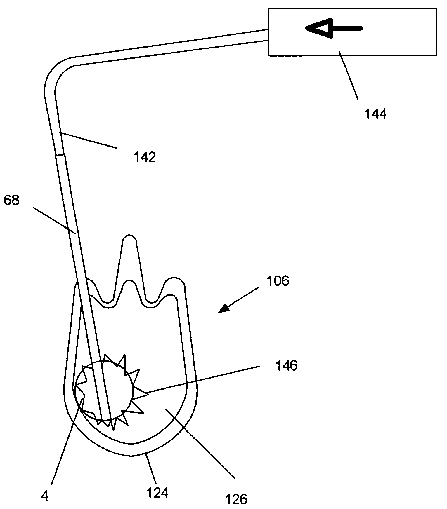
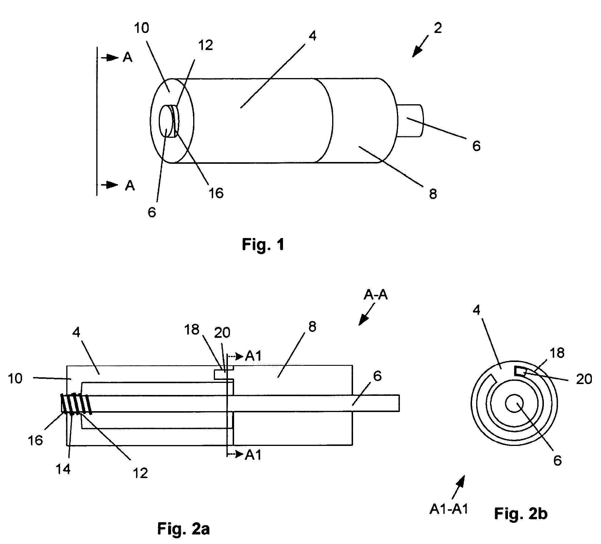
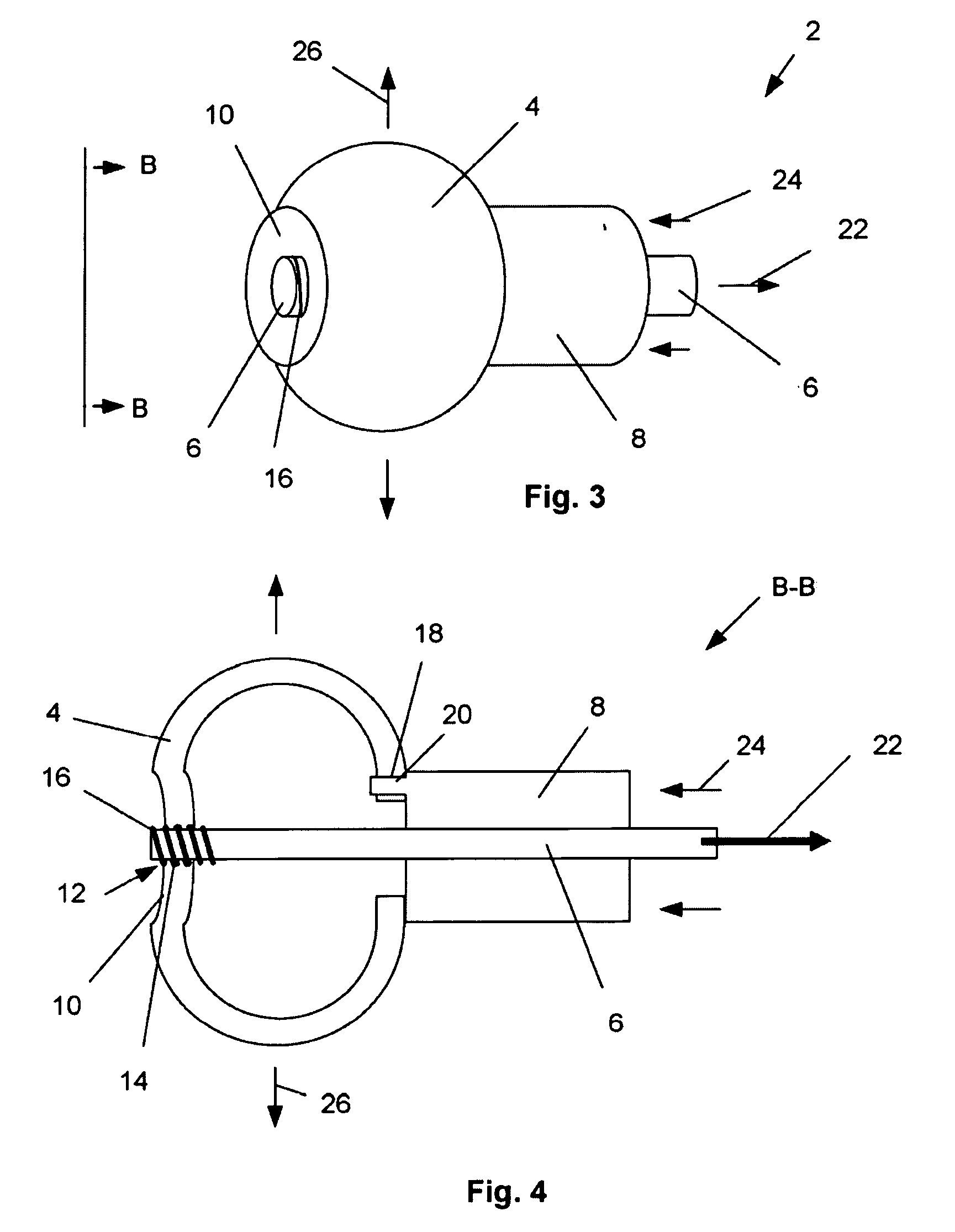
[0060]FIGS. 1, 2a and 2b illustrate a deployment system 2 that can have an expandable support device 4. The expandable support device 4 can be used, for example, as an orthopedic support device. The expandable support device 4 can be deployed, for example, between and / or within bones, such as deployment in or around the vertebra (e.g., intravertebral and / or intervertebral), phalanges, tarsals, clavicle, or other bones. The deployment system 2 can be used to treat damage to bones from trauma, disease, or combinations thereof. The deployment system 2 can have a first, longitudinally uncompressed, configuration.

[0061]The expandable support device 4 can be releasably attached to a compression apparatus, for example a rod 6 translatably attached (e.g., slidably or threadedly attached) to an anvil 8. The expandable support device 4 can have a compression and / or tensile interference fit with the anvil 8. The expandable support device 4 can releasably attach to the rod 6. The rod 6 can be i...


PUM


Abstract

A deployment system and a method of using the deployment system are disclosed. The deployment system can have an expandable support device that can be used to treat orthopedic injuries. The expandable support device can be deployed with or between bones. The deployment system can be integral with the expandable support device. The deployment system can be designed to release the expandable support device when a specific deployment force is exerted onto the deployment system.

Description

CROSS-REFERENCE TO RELATED APPLICATIONS[0001]This application is a continuation of PCT International Application No. PCT / US2006 / 062201, filed Dec. 15, 2006 which claims the benefit of U.S. Provisional Application No. 60 / 751,390, filed Dec. 15, 2005, which are both incorporated herein in their entireties.BACKGROUND OF THE INVENTION[0002]This invention relates to devices and methods for holding and deploying orthopedic and other expandable support devices (e.g., stents). The expandable support devices can be used for providing support for biological tissue, for example to repair spinal compression fractures.[0003]When performing any medical operation with an implant the implant must be delivered to the treatment site and the implant device must be properly designed and deployed. Important implant device design and deployment characteristics include size, shape, function, material, mechanical properties, and chemical properties, among others.[0004]Vertebroplasty is an image-guided, min...

Claims


Application Information

Patent Timeline
IPC IPC(8): A61F5/00A61M29/00
CPCA61F2/958
Inventor GREENHALGH, E. SKOTTROMANO, JOHN-PAUL
Owner STOUT MEDICAL GROUP
Why Eureka
Try Eureka