

Force feedback poppet valve having an integrated pressure compensator
- Summary
- Abstract
- Description
- Claims
- Application Information
AI Technical Summary
Benefits of technology
Problems solved by technology
Method used
Image

Examples
Embodiment Construction
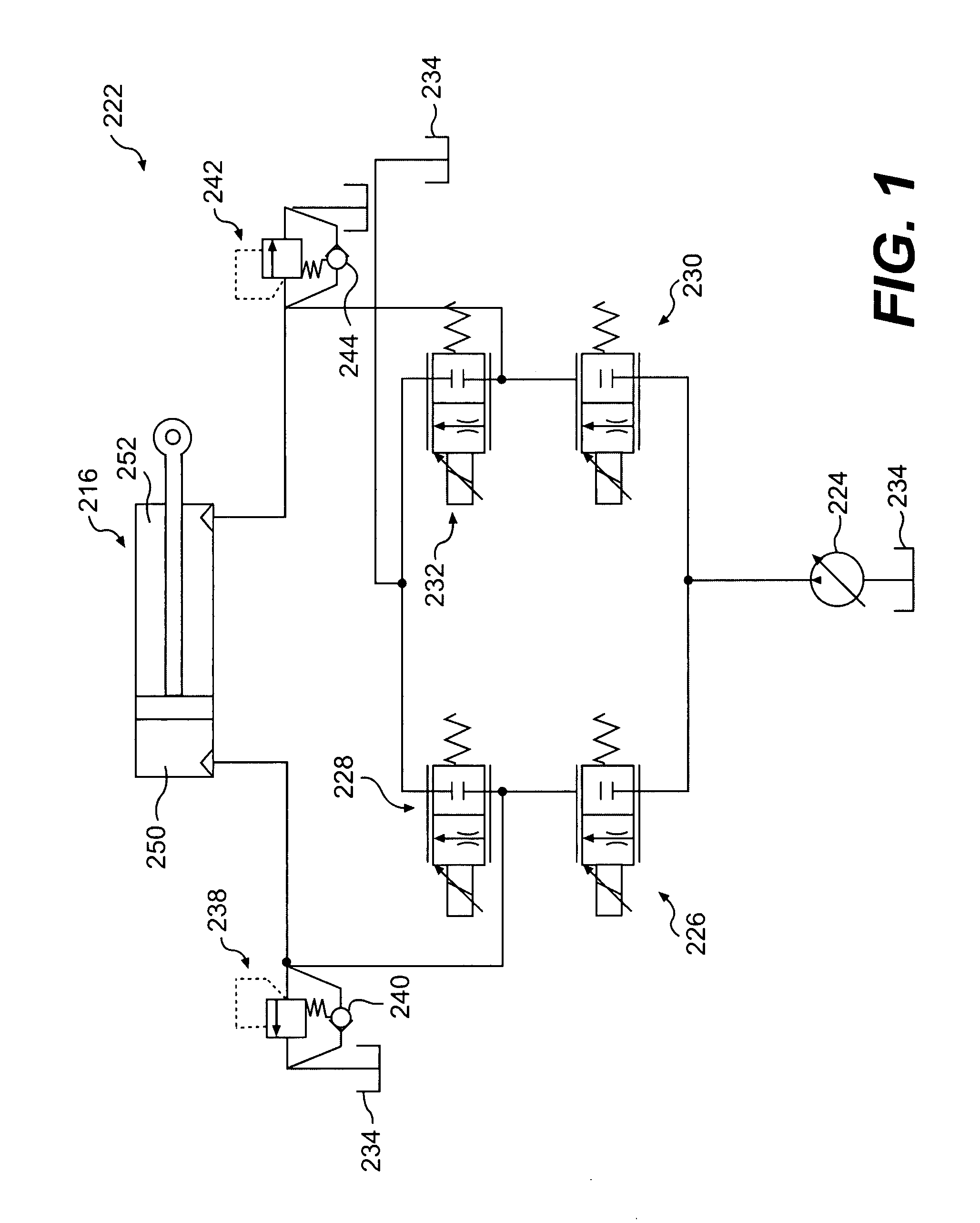
[0013]FIG. 1 illustrates a hydraulic system 222 having a hydraulic actuator 216 movable to control a work implement (not shown). Hydraulic actuator 216 may include a head-end chamber 250 and a rod-end chamber 252. Hydraulic system 222 may further include a source 224 of pressurized fluid directed to move the actuator by way of a head-end supply valve 226, a head-end drain valve 228, a rod-end supply valve 230, and a rod-end drain valve 232. Hydraulic system 222 may also include a tank 234, a head-end pressure relief valve 238, a head-end makeup valve 240, a rod-end pressure relief valve 242, and a rod-end makeup valve 244 that cooperate to maintain desired pressures within hydraulic system 222. It is contemplated that hydraulic system 222 may include additional and / or different components such as, for example, a pressure sensor, a temperature sensor, a position sensor, a controller, an accumulator, and other components known in the art.
[0014]Source 224 may produce a flow of pressuri...
PUM
 Abstract
Description
Claims
Application Information