Range finding in imaging readers for electro-optically reading indicia

an imager and indicia technology, applied in the field of imager-based readers for electro-optically reading indicia, can solve the problems of operator inability to tell, inability to use imaging readers, and known light pattern generators producing patterns that are not well visible, and achieve the effect of optimal reading performan

Inactive Publication Date: 2008-12-04
SYMBOL TECH INC
View PDF8 Cites 11 Cited by
  • Summary
  • Abstract
  • Description
  • Claims
  • Application Information

AI Technical Summary

Benefits of technology

[0014]In accordance with one feature of this invention, an optical assembly is provided for visually illuminating the target to aid an operator in aiming the imager at the target, and for visually indicating to the operator the range of working distances from the imager to the target. Thus, the optical assembly indicates the working distance range (depth of field) of the imager, as well as the optimum distance in the working range in which the target should be read for optimal reading performance.

Problems solved by technology

Although generally satisfactory for its intended purpose, the use of an imaging reader is frustrated because an operator cannot tell whether the imager, or the hand-held housing in which the imager is mounted, is aimed directly at the target symbol, which can be located anywhere within a range of working distances from the reader.
However, the known light pattern generators produce patterns that are not well visible in high ambient light conditions, such as bright sunlight.

Method used


Image

  • Range finding in imaging readers for electro-optically reading indicia
  • Range finding in imaging readers for electro-optically reading indicia
  • Range finding in imaging readers for electro-optically reading indicia

Examples


Embodiment Construction

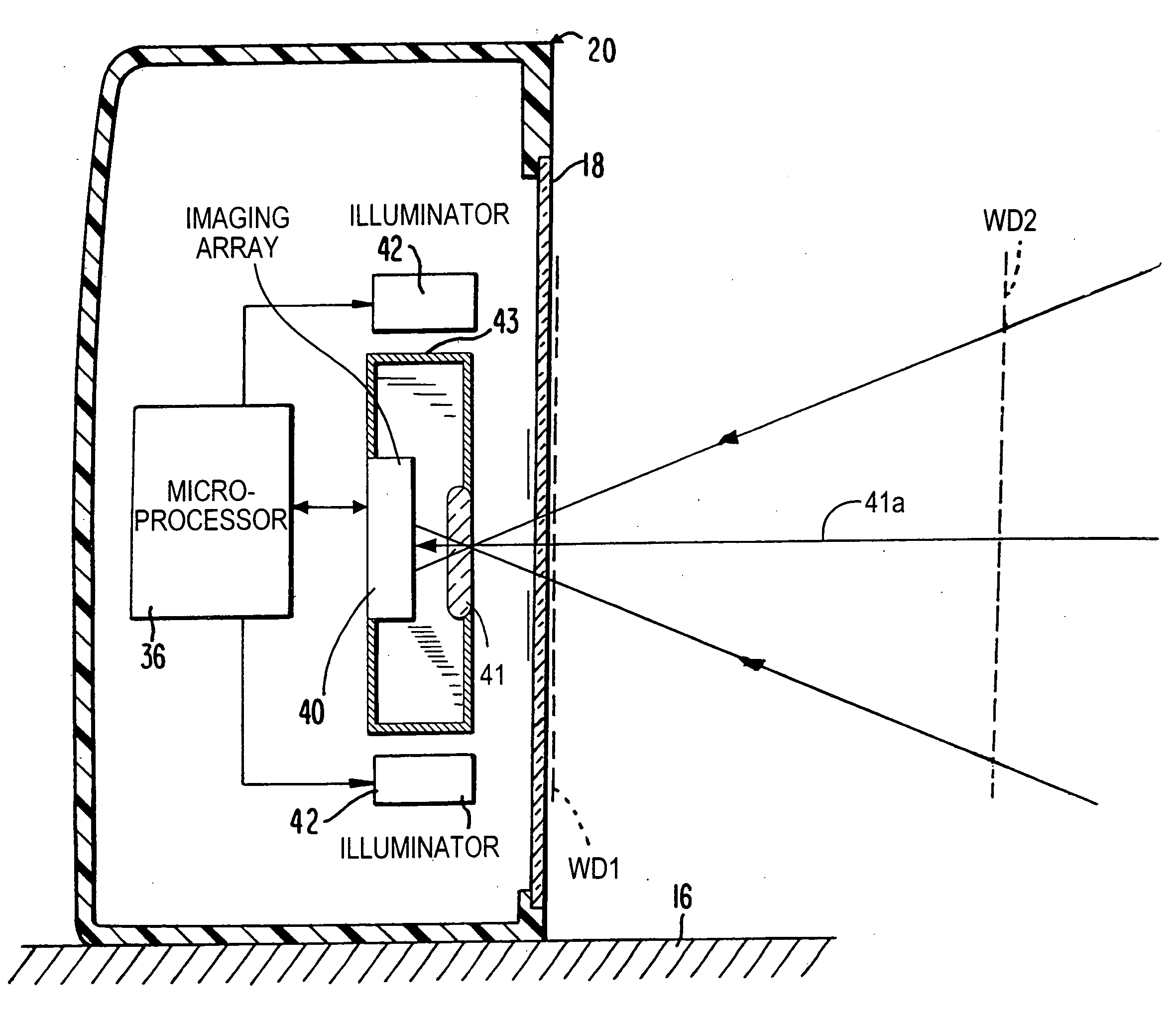
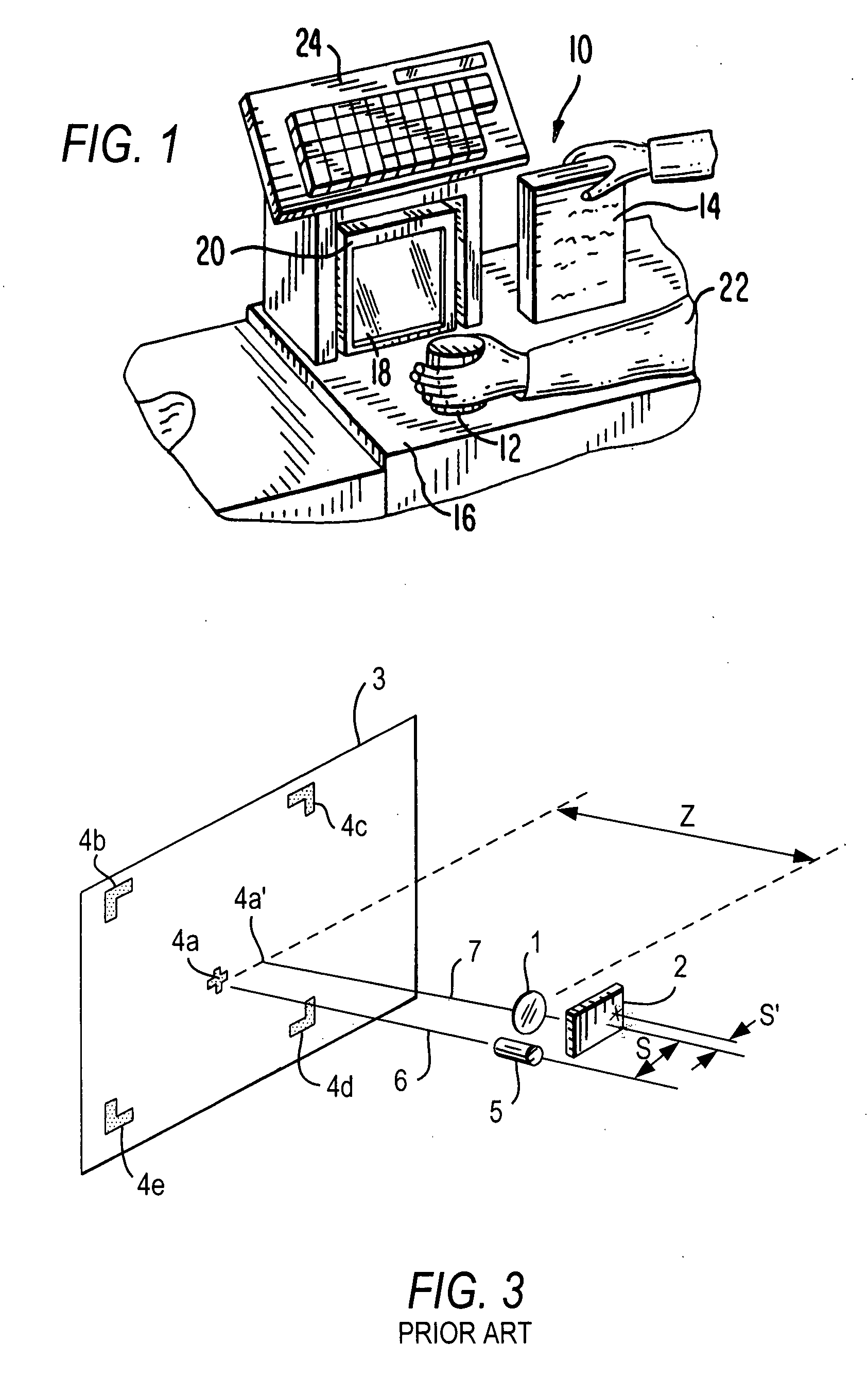
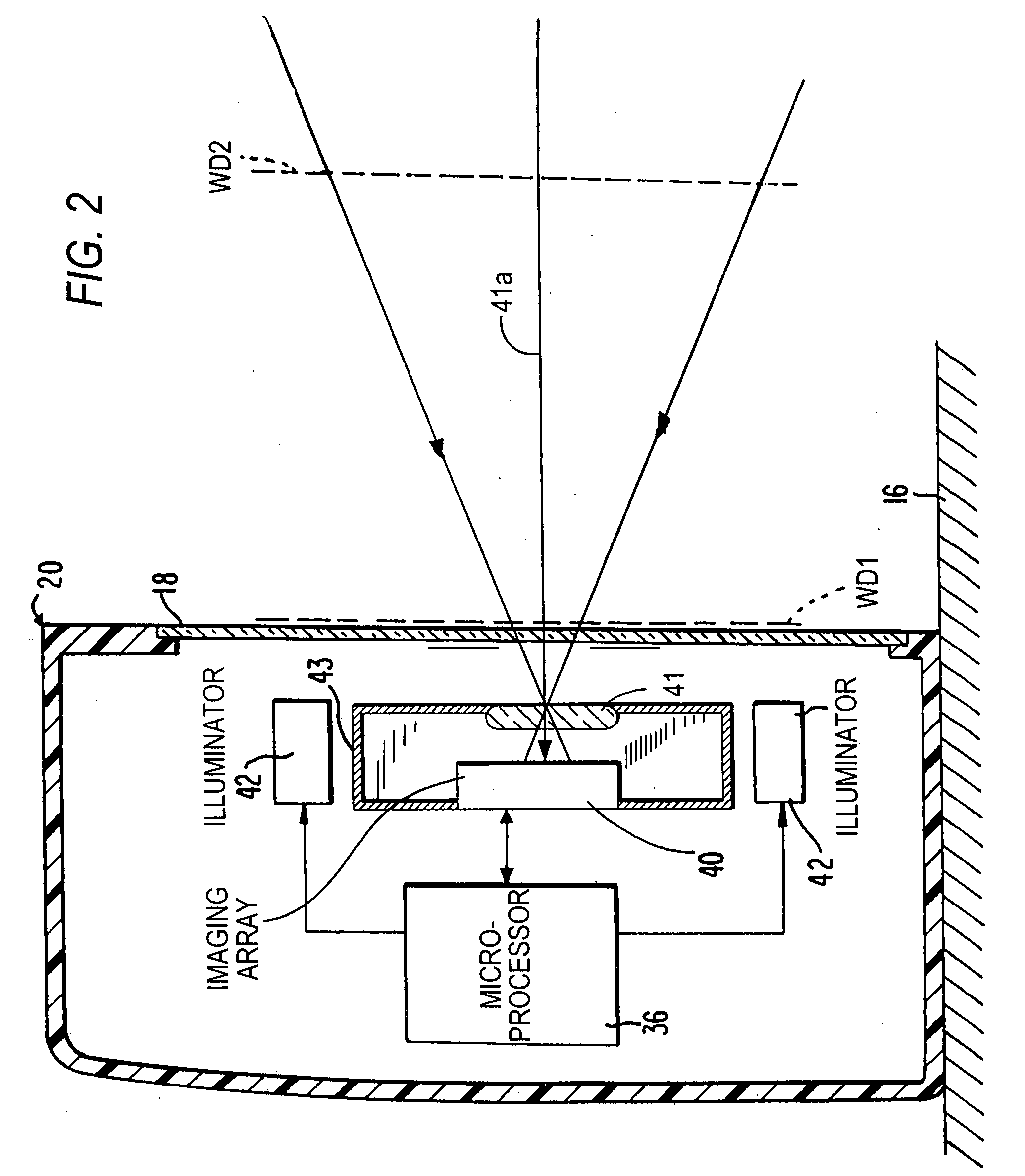
[0026]Reference numeral 10 in FIG. 1 generally identifies a workstation for processing transactions and specifically a checkout counter at a retail site at which products, such as a can 12 or a box 14, each bearing a target symbol, are processed for purchase. The counter includes a generally planar support surface or countertop 16 across which the products are slid at a swipe speed past a generally vertical window 18 of a box-shaped, vertical slot, portable imaging reader 20 mounted on the countertop 16 in a hands-free mode of operation. A checkout clerk or operator 22 is located at one side of the countertop, and the imaging reader 20 is located at the opposite side. A cash / credit register 24 is located within easy reach of the operator. In the frequent event that large, heavy, or bulky products, that cannot easily be brought to the reader 20, have target symbols that are required to be read, then the operator 22 may also manually grasp the portable reader 20 and lift it off, and r...


PUM


Abstract

In an imaging reader for reading a target located in a range of working distances from the reader, a solid-state imager captures light from the target, and an optical assembly visually illuminates the target to aid an operator in aiming the imager at the target, and also visually indicates to the operator the range of working distances from the imager to the target.

Description

BACKGROUND OF THE INVENTION[0001]1. Field of the Invention[0002]The present invention generally relates to imager-based readers for electro-optically reading indicia and, more particularly, to generating on the indicia visible light patterns indicative of a field of view and a depth of field of an imager operative for capturing light returning from the indicia.[0003]2. Description of the Related Art[0004]Optical codes or dataforms are patterns made up of image areas having different light-reflective or light-emissive properties, which are typically assembled in accordance with a priori rules. The optical properties and patterns of codes are selected to distinguish them in appearance from the background environments in which they are used. Electro-optical readers identify or extract data from codes and are used in both fixed or portable installations in many diverse environments such as in stores for check-out services, in manufacturing locations for work flow and inventory control, ...

Claims


Application Information

Patent Timeline
Patent Type & Authority Applications(United States)
IPC IPC(8): G06K7/10
CPCG06K7/10732G06K7/10792
Inventor GUREVICH, VLADIMIRBARKAN, EDWARD
Owner SYMBOL TECH INC
Why Eureka
Try Eureka