Assembly structure of a cabinet and thin display device

a technology of assembly structure and display device, which is applied in the direction of television system, selective content distribution, instruments, etc., can solve the problems of difficult detachment of front cover, inability to easily release the hooks b, and inability to easily detach the hooks /i>, etc., to achieve easy detachment of front cabinet, high degree of forming efficiency, and constant joint strength

Inactive Publication Date: 2008-12-04
FUNAI ELECTRIC CO LTD
View PDF32 Cites 12 Cited by
  • Summary
  • Abstract
  • Description
  • Claims
  • Application Information

AI Technical Summary

Benefits of technology

[0015]According to the first constitution of the present invention, when the front cabinet is put into the front cover having the side wall, the projection formed on the upper edge of the side wall of the front cabinet fits into the depression formed on the upper edge of the side wall of the front cover. Since the depression is formed on the upper edge of the side wall, and the projection is not locked by the depression in a direction opposite to a direction in which the front cabinet is attached. This makes it possible to easily detach the front cabinet from the front cover. In addition, it is possible to form the projection and the depression into simple shapes, allowing them to be formed with a die with a high degree of forming efficiency.
[0016]Furthermore, since the front cabinet is supported between the front cover and the rear cabinet, the rear cabinet is urged in a direction toward the front cover. As a result, the projection formed in the side wall of the front cabinet is pressed against the depression formed in the side wall of the front cover by the upper edge of the side wall of the rear cabinet and the protrusion protruding from the upper edge thereof in a direction in which the side wall erects. This allows the projection to be stably locked by the depression, ensuing constant joint strength between the front cabinet and the front cover.
[0017]When the rear cabinet is detached from the front cabinet, the projection is released from the pressing force received from the upper edge and the protrusion of the side wall of the rear cabinet, making it possible to easily detach the front cabinet from the front cover.
[0018]In addition, since the front cabinet is fixedly supported between the front cover and the rear cabinet, it is possible to eliminate the need for screws to fix the front cabinet and the front cover together and fix the front cabinet and the rear cabinet together.
[0019]According to the second constitution of the present invention, since the projection has a wedge shape, the projection fits into the depression more securely when pressed against it. This allows the projection to be locked by the depression more firmly. As a result, the front cover and the front cabinet are joined together more stably.
[0020]According to the third constitution of the present invention, the thin display device is provided with a cabinet having the structure described above, the cabinet inside which a display device body is placed. This makes it possible to provide the thin display device having the above-described advantages.

Problems solved by technology

However, in the course of assembly of the cabinet, once the front cover 2 and the front cabinet 3 are tightly joined together with the hooked lugs 2b fitting into the holes 3b, the hooked lugs 2b cannot be easily released from the holes 3b due to the tight fit therebetween achieved by the hook portions of the hooked lugs 2b. This makes it difficult to detach the front cover 2 from the front cabinet 3.
This necessitates extra screws, and thus increases costs of parts.
In addition, this structure increases time and labor for work with screws, reducing the efficiency of assembly.

Method used


Image

  • Assembly structure of a cabinet and thin display device
  • Assembly structure of a cabinet and thin display device
  • Assembly structure of a cabinet and thin display device

Examples


Embodiment Construction

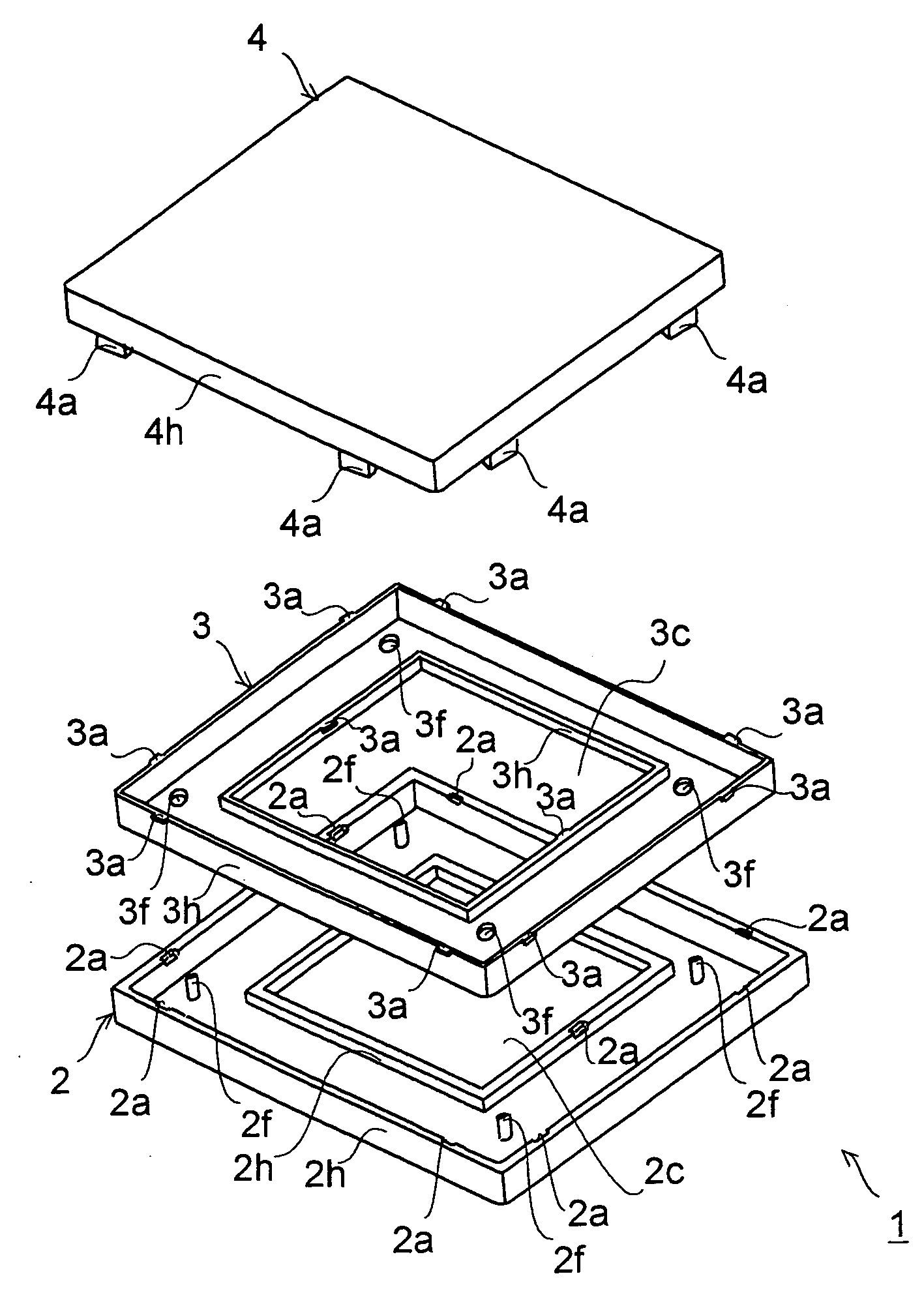
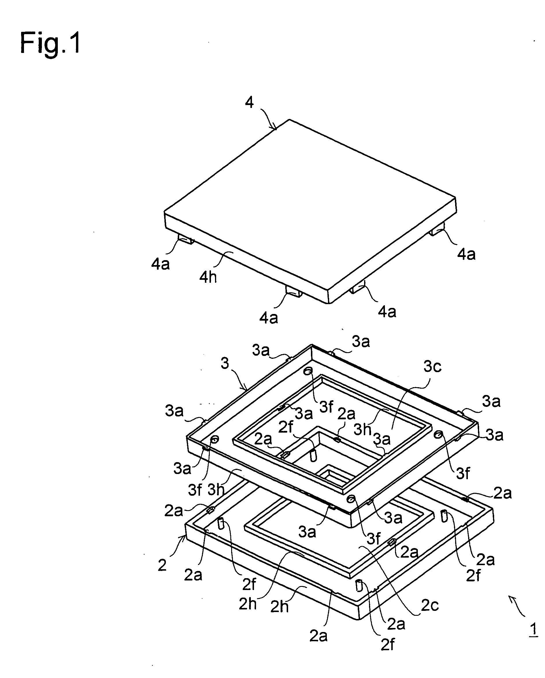
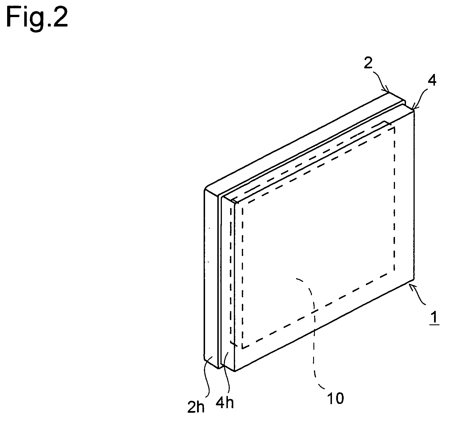
[0028]Hereinafter, preferred embodiments of the present invention will be described with reference to accompanying drawings. In the following description, such members as are found also in the conventional example shown in FIG. 7 will be identified with common reference characters, and their explanations will be omitted. In these drawings, the dimensional ratio of different structural components is made different from an actual dimensional ratio for easy understanding, and the structures of those components are not shown in detail but are only shown conceptually.

[0029]A liquid crystal display device according to an embodiment is composed of a cabinet built with a front cabinet and a rear cabinet and a liquid crystal display device body placed inside the cabinet. The liquid crystal display device body is composed of a liquid crystal display panel, a drive circuit for driving the liquid crystal display panel, a tuner for receiving a broadcast signal, and a circuit substrate on which, ...


PUM


Abstract

A projection is formed on the upper edge of the side wall of a front cabinet, a depression is formed on the upper edge of the side wall of a front cover, and a protrusion is formed on the upper edge of the side wall of a rear cabinet. The front cabinet is supported between the front cover and the rear cabinet, such that the projection of the front cabinet is pressed against the depression of the front cover by the protrusion of the rear cabinet and the upper edge of the side wall thereof, and the projection of the front cabinet is locked by the depression of the front cover.

Description

[0001]This application is based on Japanese Patent Application No. 2007-143410 filed on May 30, 2007, the contents of which are hereby incorporated by reference.BACKGROUND OF THE INVENTION[0002]1. Field of the Invention[0003]The present invention relates to assembly structures of a cabinet, and thin display devices using the cabinet.[0004]2. Description of Related Art[0005]In recent years, thin display devices, typified by liquid crystal display devices, have become commercially practical. In general, such a thin display device includes a cabinet composed of a front cabinet and a rear cabinet, and a display device body for displaying images is placed inside the cabinet. For example, in the liquid crystal display device, the display device body is composed of a liquid crystal display panel, a drive circuit for driving the liquid crystal display panel, a tuner for receiving a broadcast signal, a circuit substrate on which, for example, a control circuit for controlling different parts...

Claims


Application Information

Patent Timeline
Patent Type & Authority Applications(United States)
IPC IPC(8): A47B81/06
CPCH04N5/64H04N21/47214
Inventor IWAI, TAKEOMAKINO, KATSUHIKO
Owner FUNAI ELECTRIC CO LTD
Why Eureka
Try Eureka